Introduction to NodeMCU
NodeMCU is an open-source firmware and development board designed for IoT (Internet of Things) projects. It combines the power of the ESP8266 Wi-Fi module with a user-friendly development environment based on the Lua programming language. NodeMCU has gained popularity among hobbyists, makers, and professionals due to its ease of use, affordability, and versatility.
What is NodeMCU?
NodeMCU is a development board that integrates the ESP8266 Wi-Fi module, allowing users to create IoT applications with wireless connectivity. The board includes a USB-to-serial converter, making it easy to program and communicate with the device using a computer.
Features of NodeMCU
- ESP8266 Wi-Fi Module: NodeMCU is powered by the ESP8266 Wi-Fi module, which provides wireless connectivity and supports the IEEE 802.11 b/g/n standards.
- Lua-based Firmware: The NodeMCU firmware is based on the Lua programming language, which is known for its simplicity and ease of use.
- GPIO Pins: NodeMCU offers a set of General Purpose Input/Output (GPIO) pins that can be used to interface with various sensors, actuators, and peripherals.
- PWM and ADC: The board supports Pulse Width Modulation (PWM) and Analog-to-Digital Conversion (ADC) functionalities.
- USB-to-Serial Converter: NodeMCU includes a built-in USB-to-serial converter, allowing easy programming and communication with a computer.
NodeMCU Pinout
Understanding the pinout of NodeMCU is crucial for effectively using the board in your projects. Let’s explore the details of the NodeMCU pinout.
NodeMCU v1.0 (ESP-12E Module) Pinout
The NodeMCU v1.0 board, which uses the ESP-12E module, has the following pinout:
| Pin | Function | ESP8266 Pin |
|---|---|---|
| D0 | Digital I/O | GPIO16 |
| D1 | Digital I/O, SCL | GPIO5 |
| D2 | Digital I/O, SDA | GPIO4 |
| D3 | Digital I/O | GPIO0 |
| D4 | Digital I/O | GPIO2 |
| D5 | Digital I/O, SCK | GPIO14 |
| D6 | Digital I/O, MISO | GPIO12 |
| D7 | Digital I/O, MOSI | GPIO13 |
| D8 | Digital I/O, SS | GPIO15 |
| RX | UART Receive | GPIO3 |
| TX | UART Transmit | GPIO1 |
| A0 | Analog Input | ADC0 |
| EN | RST | RST |
| 3V3 | 3.3V Power Supply | – |
| GND | Ground | – |
| Vin | External Power Supply | – |
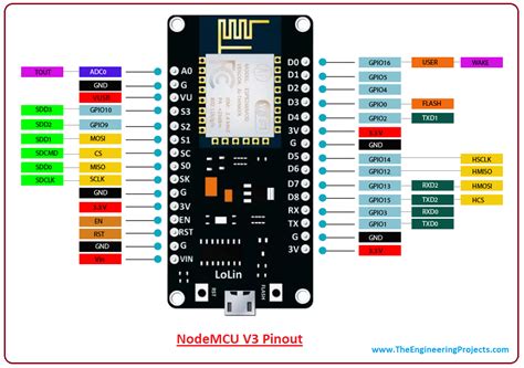
NodeMCU v3 (ESP-12E Module) Pinout
The NodeMCU v3 board, which also uses the ESP-12E module, has a slightly different pinout compared to v1.0:
| Pin | Function | ESP8266 Pin |
|---|---|---|
| D0 | Digital I/O | GPIO16 |
| D1 | Digital I/O, SCL | GPIO5 |
| D2 | Digital I/O, SDA | GPIO4 |
| D3 | Digital I/O | GPIO0 |
| D4 | Digital I/O | GPIO2 |
| D5 | Digital I/O, SCK | GPIO14 |
| D6 | Digital I/O, MISO | GPIO12 |
| D7 | Digital I/O, MOSI | GPIO13 |
| D8 | Digital I/O, SS | GPIO15 |
| D9 | Digital I/O, RX | GPIO3 |
| D10 | Digital I/O, TX | GPIO1 |
| A0 | Analog Input | ADC0 |
| EN | RST | RST |
| 3V3 | 3.3V Power Supply | – |
| GND | Ground | – |
| Vin | External Power Supply | – |
GPIO Functions
The GPIO pins on NodeMCU can be used for various purposes, such as:
- Digital Input/Output
- PWM (Pulse Width Modulation)
- I2C Communication (D1 – SCL, D2 – SDA)
- SPI Communication (D5 – SCK, D6 – MISO, D7 – MOSI, D8 – SS)
- UART Communication (RX, TX)
- Analog Input (A0)
It’s important to note that some GPIO pins have special functions and limitations. For example, GPIO16 (D0) can only be used for digital input/output and cannot be used for PWM or I2C.

Programming NodeMCU
NodeMCU can be programmed using the Lua programming language or the Arduino IDE. Let’s explore both options.
Programming with Lua
Lua is the default programming language for NodeMCU. It offers a simple and intuitive syntax, making it easy for beginners to get started with IoT projects. To program NodeMCU with Lua, you can use the ESPlorer IDE or the NodeMCU PyFlasher tool.
Here’s a simple example of a Lua script that blinks an LED connected to pin D4:
-- Set pin D4 as output
gpio.mode(2, gpio.OUTPUT)

-- Blink the LED
while true do
  gpio.write(2, gpio.HIGH)
  tmr.delay(1000000) -- Delay for 1 second
  gpio.write(2, gpio.LOW)
  tmr.delay(1000000) -- Delay for 1 second
end
Programming with Arduino IDE
NodeMCU can also be programmed using the Arduino IDE, which is a popular choice among the maker community. To use the Arduino IDE with NodeMCU, you need to install the ESP8266 board package and select the appropriate board variant.
Here’s an example of an Arduino sketch that blinks an LED connected to pin D4:
#define LED_PIN 2 // D4 pin

void setup() {
  pinMode(LED_PIN, OUTPUT);
}

void loop() {
  digitalWrite(LED_PIN, HIGH);
  delay(1000); // Delay for 1 second
  digitalWrite(LED_PIN, LOW);
  delay(1000); // Delay for 1 second
}

Example Projects
NodeMCU can be used in a wide range of IoT projects. Here are a few examples to inspire you:
1. Temperature and Humidity Sensor
You can use NodeMCU with a DHT11 or DHT22 sensor to measure temperature and humidity. Here’s a Lua script that reads the sensor data and prints it to the serial monitor:
-- Set up DHT sensor
dht_pin = 4 -- D2 pin
humidity, temperature = dht.read(dht_pin)

-- Print temperature and humidity
print("Temperature: " .. temperature .. "°C")
print("Humidity: " .. humidity .. "%")
2. Web Server
NodeMCU can be used to create a simple web server that can control LEDs or display sensor data. Here’s an example of a Lua script that creates a web server:
-- Set up Wi-Fi connection
wifi.setmode(wifi.STATION)
wifi.sta.config("SSID", "PASSWORD")

-- Set up web server
srv = net.createServer(net.TCP)
srv:listen(80, function(conn)
  conn:on("receive", function(client, request)
    -- Process the request and send a response
    client:send("HTTP/1.1 200 OK\r\nContent-Type: text/html\r\n\r\n")
    client:send("<html><body><h1>Hello from NodeMCU!</h1></body></html>")
  end)
end)
3. MQTT Client
NodeMCU can be used as an MQTT client to publish and subscribe to topics. Here’s an example of a Lua script that connects to an MQTT broker and publishes a message:
-- Set up Wi-Fi connection
wifi.setmode(wifi.STATION)
wifi.sta.config("SSID", "PASSWORD")

-- Set up MQTT client
client = mqtt.Client("NodeMCU", 120)
client:connect("MQTT_BROKER_IP", 1883, 0, function(client)
  -- Publish a message
  client:publish("topic/subtopic", "Hello from NodeMCU!", 0, 0, function(client)
    print("Message published")
  end)
end)

Frequently Asked Questions (FAQ)
1. What is the difference between NodeMCU v1.0 and v3?
The main difference between NodeMCU v1.0 and v3 is the pinout. NodeMCU v3 has a slightly different pinout compared to v1.0, with the RX and TX pins labeled as D9 and D10, respectively. However, both versions use the same ESP8266 module (ESP-12E).
2. Can I power NodeMCU using a battery?
Yes, NodeMCU can be powered using a battery. You can connect a battery to the Vin pin, which accepts a wide range of input voltages (3.3V to 5V). However, it’s recommended to use a voltage regulator to ensure a stable 3.3V supply for the ESP8266 module.
3. How do I upload code to NodeMCU?
To upload code to NodeMCU, you can use the ESPlorer IDE for Lua or the Arduino IDE for Arduino sketches. Connect NodeMCU to your computer using a USB cable, select the appropriate serial port, and click the upload button in the IDE.
4. What is the maximum current draw of NodeMCU?
The maximum current draw of NodeMCU depends on the connected peripherals and the specific application. However, the ESP8266 module itself can consume up to 250mA during peak usage, such as when transmitting data over Wi-Fi.
5. Can I use NodeMCU for battery-powered projects?
Yes, NodeMCU can be used for battery-powered projects. However, it’s important to consider power optimization techniques to extend battery life. You can use sleep modes, reduce the transmission power, and minimize the usage of power-hungry peripherals to conserve energy.
Conclusion
NodeMCU is a versatile and powerful development board that enables you to create a wide range of IoT projects. Understanding the NodeMCU pinout and its capabilities is essential for effectively using the board. With its support for Lua and Arduino programming, NodeMCU caters to both beginners and experienced developers.
By exploring the GPIO functions, programming options, and example projects, you can unleash the full potential of NodeMCU in your IoT applications. Whether you’re building a simple sensor node or a complex web-based system, NodeMCU provides a solid foundation for your projects.
Remember to refer to the NodeMCU pinout diagrams and consider the specific requirements of your project when selecting pins and peripherals. With the knowledge gained from this article, you’re ready to embark on your NodeMCU journey and create exciting IoT Solutions.
Happy coding and exploring the world of NodeMCU!


Leave a Reply