What is an Ultrasonic Sensor?
An ultrasonic sensor is an electronic device that emits high-frequency sound waves and measures the time taken for the waves to bounce back from an object. By calculating the time of flight and the speed of sound, the sensor can determine the distance between itself and the object. Ultrasonic sensors typically operate at frequencies above 20 kHz, which is beyond the range of human hearing.
Key Components of an Ultrasonic Sensor
An ultrasonic sensor consists of the following main components:
-
Transmitter: The transmitter is responsible for generating the high-frequency sound waves. It typically consists of a piezoelectric transducer that converts electrical energy into mechanical energy, producing the ultrasonic waves.
-
Receiver: The receiver is another piezoelectric transducer that converts the reflected sound waves back into electrical signals. It detects the echo of the transmitted waves and generates an output signal.
-
Control Circuit: The control circuit manages the timing and triggering of the transmitter and receiver. It generates the necessary pulses to activate the transmitter and measures the time duration between the transmitted and received signals.
-
Signal Conditioning Circuit: The signal conditioning circuit processes the received signals, amplifying and filtering them to extract the relevant information. It may include amplifiers, comparators, and digital signal processing units.
Working Principle of an Ultrasonic Sensor
The working principle of an ultrasonic sensor can be summarized in the following steps:
- The control circuit triggers the transmitter to generate a short burst of high-frequency sound waves.
- The sound waves travel through the medium (usually air) at the speed of sound.
- When the waves encounter an object, they reflect back towards the sensor.
- The receiver detects the reflected waves and generates an electrical signal.
- The control circuit measures the time interval between the transmitted and received signals.
- Using the known speed of sound and the measured time interval, the distance to the object can be calculated using the formula: Distance = (Speed of Sound × Time) / 2.
Ultrasonic Sensor Circuit Design
Designing an ultrasonic sensor circuit involves several key components and considerations. Let’s explore the essential elements of an ultrasonic sensor circuit.
Transmitter Circuit
The transmitter circuit generates the high-frequency sound waves. It typically consists of a piezoelectric transducer driven by a pulse generator. The pulse generator produces short electrical pulses that cause the transducer to vibrate at its resonant frequency, generating the ultrasonic waves.
A common transmitter circuit configuration includes:
– A microcontroller or pulse generator IC to generate the trigger pulses
– A driver circuit (e.g., transistor, MOSFET) to amplify the pulses and drive the transducer
– A matching network to optimize the power transfer to the transducer
Receiver Circuit
The receiver circuit detects the reflected ultrasonic waves and converts them into electrical signals. It typically consists of another piezoelectric transducer that acts as a microphone, converting the mechanical vibrations into electrical signals.
The receiver circuit may include the following components:
– A preamplifier to amplify the weak received signals
– A bandpass filter to remove noise and unwanted frequencies
– An envelope detector or comparator to extract the timing information
Control and Signal Processing Circuit
The control and signal processing circuit manages the overall operation of the ultrasonic sensor. It generates the trigger pulses for the transmitter, measures the time of flight, and calculates the distance based on the received signals.
Key components of the control and signal processing circuit include:
– A microcontroller or dedicated ultrasonic sensor IC
– Timing and counting modules to measure the time of flight
– Analog-to-digital converters (ADCs) to digitize the received signals
– Digital signal processing units for filtering and analysis
Here’s an example of a basic ultrasonic sensor circuit schematic:
        +5V
         |
        +-+
        | |
        | |  Transmitter
        | |  Transducer
        | |
        +-+
         |
         |
        +-+
        | |
        | |  Receiver
        | |  Transducer
        | |
        +-+
         |
         |
       +-+-+
       |   |
       |   |  Microcontroller
       |   |
       +-+-+
         |
         |
      +--+--+
      |     |
      | ADC |
      |     |
      +--+--+
         |
         |
      Output
In this schematic, the microcontroller generates the trigger pulses for the transmitter transducer and measures the time of flight. The received signals from the receiver transducer are amplified and digitized by the ADC, and the microcontroller processes the data to calculate the distance.

Ultrasonic Sensor Applications
Ultrasonic sensors find applications in a wide range of fields due to their non-contact, precise, and reliable distance measurement capabilities. Some common applications include:
-
Distance Measurement: Ultrasonic sensors are widely used for distance measurement in various scenarios, such as measuring the level of liquids in tanks, determining the height of objects, or monitoring the distance between vehicles in parking systems.
-
Object Detection: Ultrasonic sensors can detect the presence or absence of objects within their sensing range. This is useful in applications like obstacle avoidance in robotics, collision detection in vehicles, or presence detection in security systems.
-
Proximity Sensing: Ultrasonic sensors excel at proximity sensing, where they can detect the proximity of objects or people. This is valuable in applications like automatic doors, touchless interfaces, or gesture recognition systems.
-
Level Measurement: Ultrasonic sensors are commonly used for level measurement in tanks, silos, or containers. They provide a non-contact method of measuring the level of liquids, powders, or granular materials, enabling accurate monitoring and control.
-
Robotics and Automation: Ultrasonic sensors are extensively used in robotics and automation systems. They help robots navigate, avoid obstacles, and interact with their environment. Ultrasonic sensors are often used in combination with other sensors like infrared or vision systems.
-
Automotive Applications: Ultrasonic sensors find applications in various automotive systems, such as parking assistance, blind-spot detection, and collision avoidance. They assist drivers by providing distance information and alerts.
-
Industrial Automation: In industrial settings, ultrasonic sensors are used for various purposes, including quality control, material handling, and process monitoring. They can detect defects, measure dimensions, or monitor the flow of materials on conveyor belts.

Implementing an Ultrasonic Sensor Circuit
Now that we have covered the basics of ultrasonic sensor circuits and their applications, let’s dive into the practical implementation of an ultrasonic sensor circuit using a popular ultrasonic sensor module: the HC-SR04.
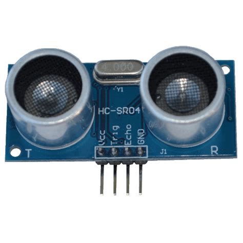
HC-SR04 Ultrasonic Sensor Module
The HC-SR04 is a widely used ultrasonic sensor module that provides an easy-to-use interface for distance measurement. It consists of a transmitter and a receiver transducer, along with the necessary control circuitry.
Key features of the HC-SR04 module:
– Operating voltage: 5V DC
– Operating current: 15mA
– Measurement range: 2cm to 400cm
– Accuracy: ±3mm
– Measuring angle: 15 degrees
– Trigger input pulse width: 10µs
– Dimensions: 45mm × 20mm × 15mm
Connecting the HC-SR04 to a Microcontroller
To use the HC-SR04 module with a microcontroller, you need to make the following connections:
| HC-SR04 Pin | Microcontroller Pin |
|---|---|
| VCC | 5V |
| Trig | Digital Output |
| Echo | Digital Input |
| GND | GND |
Here’s an example connection diagram using an Arduino Microcontroller:
   HC-SR04      Arduino
   -------      -------
     VCC   ->   5V
     Trig  ->   Digital Pin 10
     Echo  ->   Digital Pin 11
     GND   ->   GND
Arduino Code for Distance Measurement
Here’s a sample Arduino code that demonstrates how to measure distance using the HC-SR04 ultrasonic sensor:
const int trigPin = 10;
const int echoPin = 11;

void setup() {
  pinMode(trigPin, OUTPUT);
  pinMode(echoPin, INPUT);
  Serial.begin(9600);
}

void loop() {
  // Generate a 10µs trigger pulse
  digitalWrite(trigPin, LOW);
  delayMicroseconds(2);
  digitalWrite(trigPin, HIGH);
  delayMicroseconds(10);
  digitalWrite(trigPin, LOW);

  // Measure the duration of the echo pulse
  long duration = pulseIn(echoPin, HIGH);

  // Calculate the distance in centimeters
  int distance = duration * 0.034 / 2;

  // Print the distance to the serial monitor
  Serial.print("Distance: ");
  Serial.print(distance);
  Serial.println(" cm");

  delay(100);
}
In this code:
1. We define the trigger and echo pins connected to the HC-SR04 module.
2. In the setup() function, we initialize the trigger pin as an output and the echo pin as an input. We also start the serial communication.
3. In the loop() function, we generate a 10µs trigger pulse by setting the trigger pin HIGH for 10µs and then LOW.
4. We measure the duration of the echo pulse using the pulseIn() function, which waits for the echo pin to go HIGH and returns the duration in microseconds.
5. We calculate the distance in centimeters using the formula: Distance = (Duration × Speed of Sound) / 2. The speed of sound is approximately 340 m/s or 0.034 cm/µs.
6. Finally, we print the calculated distance to the serial monitor.
By uploading this code to the Arduino and opening the serial monitor, you can observe the measured distance in real-time.

Frequently Asked Questions (FAQ)
-
What is the maximum range of an ultrasonic sensor?
The maximum range of an ultrasonic sensor depends on the specific sensor model and its specifications. Typically, ultrasonic sensors have a range of a few centimeters to several meters. For example, the HC-SR04 module has a range of 2cm to 400cm. -
How accurate are ultrasonic sensors?
Ultrasonic sensors provide relatively accurate distance measurements. The accuracy can vary based on factors like the sensor’s resolution, signal strength, and environmental conditions. Most ultrasonic sensors have an accuracy of a few millimeters to a few centimeters. -
Can ultrasonic sensors detect transparent objects?
Yes, ultrasonic sensors can detect transparent objects as long as they have a sufficient acoustic reflectivity. The sound waves emitted by the sensor will reflect off the surface of the transparent object, allowing the sensor to detect its presence and measure the distance. -
Are ultrasonic sensors affected by ambient noise?
Ultrasonic sensors can be affected by ambient noise, especially if the noise contains frequencies similar to the sensor’s operating frequency. However, most ultrasonic sensors have a narrow frequency range and use filtering techniques to minimize the impact of ambient noise. -
Can ultrasonic sensors work in liquid media?
Yes, ultrasonic sensors can work in liquid media, such as water or oil. In fact, ultrasonic sensors are commonly used for level measurement in tanks and containers. However, the sensor’s performance may be affected by factors like the liquid’s viscosity, density, and the presence of bubbles or particles.
Conclusion
Ultrasonic sensor circuits provide a powerful and versatile solution for distance measurement and object detection. By understanding the working principles, components, and applications of ultrasonic sensors, you can effectively integrate them into your projects and develop innovative solutions.
In this comprehensive guide, we covered the fundamentals of ultrasonic sensors, including their key components, working principle, and circuit design considerations. We explored various applications of ultrasonic sensors, ranging from distance measurement and object detection to robotics and automation.
We also provided a practical example of implementing an ultrasonic sensor circuit using the popular HC-SR04 module and an Arduino microcontroller. By following the connection diagram and sample code, you can quickly get started with ultrasonic sensing in your own projects.
As you delve deeper into the world of ultrasonic sensors, you may encounter more advanced topics like signal processing, noise reduction, and sensor fusion. There are numerous resources available, including datasheets, application notes, and online communities, that can help you expand your knowledge and tackle more complex challenges.
Remember, ultrasonic sensors are just one tool in the vast array of sensing technologies available. Depending on your specific application requirements, you may need to combine ultrasonic sensors with other sensors like infrared, laser, or vision systems to achieve optimal results.
So, go ahead and explore the exciting possibilities of ultrasonic sensor circuits. With creativity and a solid understanding of the underlying principles, you can develop innovative solutions that push the boundaries of distance measurement and object detection.


Leave a Reply