Introduction to TRIAC Symbols
TRIAC (TRIode for Alternating Current) is a semiconductor device widely used in power control applications, such as dimming lights, controlling motor speeds, and regulating temperature in heating systems. As an essential component in electronic circuits, understanding TRIAC symbols is crucial for beginners in the field of electronics. This comprehensive guide will take you through the fundamentals of TRIAC symbols, their variations, and their applications in various circuits.
What is a TRIAC?
A TRIAC is a three-terminal, bidirectional semiconductor switch that can conduct current in both directions when triggered by a small gate current. It is an extension of the thyristor family and is commonly used in AC power control applications. The three terminals of a TRIAC are:
- Main Terminal 1 (MT1)
- Main Terminal 2 (MT2)
- Gate (G)
When a TRIAC is triggered by applying a small current to its gate terminal, it allows current to flow between MT1 and MT2 in either direction, depending on the polarity of the voltage across the main terminals.
Advantages of using TRIACs
TRIACs offer several advantages over other power control devices, such as relays and mechanical switches:
- Solid-state construction: TRIACs have no moving parts, making them more reliable and durable than mechanical switches.
- Fast switching: TRIACs can switch on and off very quickly, allowing for precise power control.
- Silent operation: Unlike relays, TRIACs operate silently, making them suitable for use in noise-sensitive applications.
- Compact size: TRIACs are available in small packages, making them ideal for space-constrained designs.
- Low power consumption: TRIACs require very little power to control large loads, making them energy-efficient.
TRIAC Symbol Variations
TRIAC symbols may vary slightly depending on the manufacturer or the standard being followed. However, the basic structure of the symbol remains the same. Below are some common variations of the TRIAC symbol:
Basic TRIAC Symbol
The basic TRIAC symbol consists of two back-to-back thyristor symbols connected in parallel, with a gate terminal attached to the junction point. The main terminals are labeled MT1 and MT2, while the gate terminal is labeled G.
IEC TRIAC Symbol
The International Electrotechnical Commission (IEC) defines a standardized symbol for TRIACs. In this representation, the gate terminal is shown as a single line extending from the center of the parallel thyristor symbols. The main terminals are labeled A1 and A2, representing anode 1 and anode 2, respectively.
IEEE TRIAC Symbol
The Institute of Electrical and Electronics Engineers (IEEE) uses a slightly different symbol for TRIACs. In this representation, the gate terminal is shown as a small circle connected to the center of the parallel thyristor symbols. The main terminals are labeled T1 and T2, representing terminal 1 and terminal 2, respectively.
Comparison of TRIAC Symbol Variations
| Symbol Variation | Main Terminal 1 | Main Terminal 2 | Gate Terminal |
|---|---|---|---|
| Basic | MT1 | MT2 | G |
| IEC | A1 | A2 | G |
| IEEE | T1 | T2 | G |
Despite the slight differences in labeling and representation, all TRIAC symbols convey the same basic structure and function of the device.

TRIAC Operation and Characteristics
To effectively use TRIACs in electronic circuits, it is essential to understand their operation and characteristics. This section will cover the basics of TRIAC triggering, quadrant operation, and important parameters.
TRIAC Triggering
A TRIAC is triggered into conduction by applying a small current to its gate terminal. The gate current can be either positive or negative, depending on the desired direction of current flow between the main terminals. There are four possible triggering modes for a TRIAC:
- Quadrant I: Positive gate current, positive MT2 voltage with respect to MT1
- Quadrant II: Negative gate current, positive MT2 voltage with respect to MT1
- Quadrant III: Negative gate current, negative MT2 voltage with respect to MT1
- Quadrant IV: Positive gate current, negative MT2 voltage with respect to MT1
Once triggered, the TRIAC will remain in conduction until the current flowing through the main terminals drops below a certain level, known as the holding current.
TRIAC Quadrant Operation
TRIACs are capable of conducting current in both directions, depending on the polarity of the voltage across the main terminals and the gate triggering current. The four quadrants of operation are:
| Quadrant | MT2 Voltage | Gate Current |
|---|---|---|
| I | Positive | Positive |
| II | Positive | Negative |
| III | Negative | Negative |
| IV | Negative | Positive |
In most applications, TRIACs are triggered in quadrants I and III, allowing for full-wave control of AC loads.
Important TRIAC Parameters
When selecting a TRIAC for a specific application, several key parameters must be considered:
- Voltage Rating: The maximum voltage that can be applied across the main terminals without causing damage to the device.
- Current Rating: The maximum current that the TRIAC can handle continuously without overheating.
- Gate Trigger Current (IGT): The minimum gate current required to trigger the TRIAC into conduction.
- Gate Trigger Voltage (VGT): The minimum voltage required at the gate to trigger the TRIAC into conduction.
- Holding Current (IH): The minimum current required to maintain the TRIAC in conduction after triggering.
- dV/dt Rating: The maximum rate of change of voltage across the main terminals that the TRIAC can withstand without self-triggering.
Understanding these parameters is crucial for proper TRIAC selection and circuit design.

TRIAC Applications and Circuit Diagrams
TRIACs find applications in a wide range of power control circuits, from simple light dimmers to complex motor speed controllers. This section will explore some common TRIAC applications and their corresponding circuit diagrams.
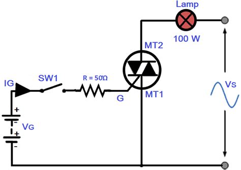
Light Dimmer Circuit
One of the most basic TRIAC applications is a light dimmer circuit. In this circuit, a TRIAC is used to control the power delivered to a lamp, allowing the user to adjust the brightness. The gate of the TRIAC is triggered by a variable phase control circuit, typically consisting of a potentiometer and a DIAC.
Motor Speed Control Circuit
TRIACs can also be used to control the speed of AC motors by adjusting the power delivered to the motor windings. In a simple motor speed control circuit, a TRIAC is triggered by a phase control circuit similar to that used in a light dimmer. The power delivered to the motor is varied by adjusting the phase angle at which the TRIAC is triggered in each AC cycle.
Temperature Control Circuit
In temperature control applications, TRIACs are used to regulate the power delivered to heating elements, such as in electric ovens or soldering irons. The TRIAC is triggered by a temperature sensing circuit, which compares the desired temperature with the actual temperature measured by a sensor, such as a thermistor or thermocouple.
These are just a few examples of the many applications where TRIACs are used for power control. By understanding TRIAC symbols and their operation, beginners can design and troubleshoot a wide range of power control circuits.

TRIAC Protection and Safety Considerations
When working with TRIACs, it is essential to consider protection and safety measures to ensure reliable operation and prevent damage to the device or other Circuit Components. This section will discuss common protection techniques and safety considerations when using TRIACs.
Snubber Circuits
TRIACs are sensitive to rapid changes in voltage across their main terminals, which can cause unwanted triggering or device failure. To mitigate this issue, snubber circuits are often used in parallel with the TRIAC. A snubber circuit typically consists of a resistor and a capacitor in series, which limit the rate of change of voltage (dV/dt) across the TRIAC.
Gate Protection
The gate of a TRIAC is sensitive to overvoltage and overcurrent conditions. To protect the gate, a current-limiting resistor is usually placed in series with the gate terminal. Additionally, a parallel combination of a resistor and a capacitor can be used to suppress high-frequency noise that may cause unwanted triggering.
Heatsinking
TRIACs dissipate power in the form of heat during operation, especially when controlling large loads. To prevent overheating and ensure reliable operation, it is crucial to provide adequate heatsinking. Heatsinks are designed to efficiently transfer heat away from the TRIAC and into the surrounding air. The size and type of heatsink required depend on the power dissipation of the TRIAC and the ambient temperature.
Isolation and Safety
When working with high-voltage AC circuits, isolation and safety are paramount. TRIACs should be isolated from the low-voltage control circuitry using optocouplers or pulse transformers. This ensures that any high-voltage faults or transients do not damage the control circuitry or pose a safety risk to users. Additionally, proper grounding and fusing should be employed to protect against electric shock and fire hazards.
By incorporating these protection measures and following safety guidelines, designers can create robust and reliable power control circuits using TRIACs.
Troubleshooting TRIAC Circuits
Despite careful design and protection measures, TRIAC circuits may sometimes malfunction. This section will provide a brief overview of common issues and troubleshooting techniques for TRIAC circuits.
TRIAC Not Triggering
If a TRIAC is not triggering, the first step is to check the gate triggering circuit. Ensure that the gate is receiving the correct triggering voltage and current. Check the gate resistor and any other components in the triggering circuit for proper values and functionality. Also, verify that the TRIAC is being triggered in the correct quadrant for the desired operation.
TRIAC Overheating
If a TRIAC is overheating, it may be due to insufficient heatsinking or excessive power dissipation. Check that the heatsink is properly sized and mounted, and ensure that the TRIAC is not being operated beyond its rated current and voltage. In some cases, a snubber circuit may be necessary to limit the rate of change of voltage across the TRIAC and reduce power dissipation.
Load Not Responding
If the load controlled by the TRIAC is not responding as expected, first verify that the TRIAC is triggering properly. Check the load for any faults or open circuits. In some cases, the load may require a minimum holding current to remain in conduction, which can be ensured by using a suitable triggering circuit or by adding a parallel resistor to the load.
EMI and Interference
TRIACs can generate electromagnetic interference (EMI) due to their fast switching nature. This can cause problems in nearby sensitive electronic circuits. To minimize EMI, use proper shielding and grounding techniques, and consider adding snubber circuits or soft-switching techniques to reduce the rate of change of voltage and current during switching.
By understanding common issues and applying systematic troubleshooting techniques, designers can quickly identify and resolve problems in TRIAC circuits.
Frequently Asked Questions (FAQs)
-
Q: What is the difference between a TRIAC and a thyristor?
A: While both TRIACs and thyristors are used for power control, a thyristor is a unidirectional device that can only conduct current in one direction. A TRIAC, on the other hand, is a bidirectional device that can conduct current in both directions, making it more suitable for AC power control applications. -
Q: Can a TRIAC be used to control DC loads?
A: No, TRIACs are designed specifically for AC power control. For controlling DC loads, other devices such as transistors, MOSFETs, or DC solid-state relays should be used. -
Q: What happens if a TRIAC is triggered without a load connected?
A: If a TRIAC is triggered without a load connected, it will not conduct current, as there is no complete path for the current to flow. However, this situation does not typically cause damage to the TRIAC, as long as the maximum voltage and dV/dt ratings are not exceeded. -
Q: How do I select the appropriate TRIAC for my application?
A: When selecting a TRIAC, consider the following factors: voltage rating, current rating, gate trigger current and voltage, holding current, and dV/dt rating. The TRIAC should be rated to handle the maximum expected voltage and current in your application, and the triggering circuit should be designed to provide the necessary gate current and voltage. -
Q: Can multiple TRIACs be used in parallel for higher current capacity?
A: While it is possible to use multiple TRIACs in parallel to increase current capacity, it is not recommended. TRIACs may not share current evenly due to variations in device characteristics, leading to overheating and potential failure. If higher current capacity is required, it is better to use a single TRIAC with a higher current rating or consider alternative power control methods, such as power transistors or IGBTs.
Conclusion
This comprehensive guide has covered the fundamentals of TRIAC symbols, operation, and applications. By understanding TRIAC symbol variations, triggering modes, and key parameters, beginners can effectively design and troubleshoot power control circuits using these versatile devices.
Remember to consider protection measures such as snubber circuits, gate protection, and proper heatsinking to ensure reliable and safe operation. When troubleshooting TRIAC circuits, systematically check the triggering circuit, power dissipation, load characteristics, and potential sources of interference.
As with any high-voltage AC circuit, always prioritize safety by using proper isolation techniques and following established guidelines. With a solid understanding of TRIAC symbols and their applications, beginners can confidently tackle a wide range of power control projects and continue to expand their knowledge in the fascinating field of electronics.


Leave a Reply