Introduction to Buzzer Circuits
A buzzer circuit is an electronic device that produces sound when powered by electricity. Buzzers are commonly used in alarms, timers, and other applications where an audible alert or notification is needed. In this article, we will explore the basics of buzzer circuits, how to create a simple design, and ways to enhance its functionality.
What is a Buzzer?
A buzzer is an audio signaling device that can be mechanical, electromechanical, or piezoelectric. The most common type used in electronic circuits is the piezoelectric buzzer, which consists of a piezoelectric crystal that vibrates when an electric current is applied. This vibration creates a sound wave that we perceive as a buzz or beep.
Types of Buzzers
There are two main types of buzzers:
-
Active Buzzers: These buzzers have a built-in oscillating circuit that generates the sound when powered. They typically operate at a specific frequency and only require a DC voltage to function.
-
Passive Buzzers: These buzzers do not have an internal oscillator and require an external AC signal to produce sound. The frequency and tone of the sound depend on the input signal provided.
Basic Buzzer Circuit Design
Components Required
To create a simple buzzer circuit, you will need the following components:
| Component | Quantity |
|---|---|
| Piezoelectric Buzzer | 1 |
| Resistor (1kΩ) | 1 |
| Transistor (BC547) | 1 |
| Pushbutton Switch | 1 |
| Battery (9V) | 1 |
| Breadboard | 1 |
| Jumper Wires | As needed |
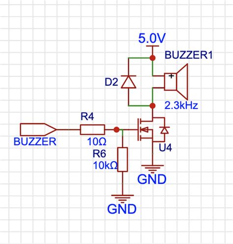
Circuit Diagram
Here is a simple circuit diagram for a buzzer circuit:
Step-by-Step Instructions
- Place the components on the breadboard according to the circuit diagram.
- Connect the positive terminal of the battery to one end of the pushbutton switch.
- Connect the other end of the pushbutton switch to the base of the transistor through a 1kΩ resistor.
- Connect the emitter of the transistor to the ground (negative terminal of the battery).
- Connect one lead of the buzzer to the collector of the transistor.
- Connect the other lead of the buzzer to the positive terminal of the battery.
Now, when you press the pushbutton switch, the buzzer will sound. Releasing the button will stop the buzzer.

Enhancing the Buzzer Circuit
Adding an LED Indicator
To add a visual indication when the buzzer is active, you can include an LED in parallel with the buzzer. Here’s how to modify the circuit:
- Connect the anode (positive lead) of the LED to the collector of the transistor.
- Connect the cathode (negative lead) of the LED to the ground through a current-limiting resistor (e.g., 330Ω).
Now, when the buzzer is active, the LED will light up, providing a visual cue along with the audible alert.
Creating a Melody with a Passive Buzzer
To create a melody using a passive buzzer, you’ll need a microcontroller (e.g., Arduino) to generate the required AC signal. Here’s a basic example using an Arduino:
- Connect one lead of the passive buzzer to an Arduino digital pin (e.g., pin 8).
- Connect the other lead of the buzzer to the ground.
- Upload the following code to the Arduino:
const int BUZZER_PIN = 8;

void setup() {
  pinMode(BUZZER_PIN, OUTPUT);
}

void loop() {
  tone(BUZZER_PIN, 440, 500); // Play a 440Hz tone for 500ms
  delay(500);
  tone(BUZZER_PIN, 523, 500); // Play a 523Hz tone for 500ms
  delay(500);
}
This code will play a simple two-note melody repeatedly using the passive buzzer connected to pin 8.
Adjusting the Buzzer Volume
To adjust the volume of an active buzzer, you can use a potentiometer to vary the voltage supplied to the buzzer. Follow these steps:
- Connect one end of the potentiometer to the positive terminal of the battery.
- Connect the other end of the potentiometer to the ground.
- Connect the wiper (middle pin) of the potentiometer to one lead of the buzzer.
- Connect the other lead of the buzzer to the collector of the transistor, as in the basic circuit.
Rotating the potentiometer will change the voltage supplied to the buzzer, thus adjusting its volume.

Troubleshooting
Buzzer Not Working
If your buzzer circuit is not working, check the following:
- Ensure all connections are correct and secure.
- Verify that the battery is properly connected and has sufficient charge.
- Check the polarity of the buzzer and ensure it is connected correctly.
- Test the buzzer separately with a battery to confirm it is functional.
- Replace the transistor if it is damaged or faulty.
Buzzer is Too Loud or Too Quiet
If the buzzer volume is not suitable, consider these solutions:
- For an active buzzer, use a potentiometer to adjust the voltage supplied to the buzzer, as described in the “Adjusting the Buzzer Volume” section.
- For a passive buzzer, modify the code to change the tone duration or frequency to achieve the desired volume.
- Use a different buzzer with a more appropriate sound level for your application.

Applications
Buzzer circuits have a wide range of applications, including:
-
Alarm Systems: Buzzers are commonly used in alarm systems to alert users of intrusion, fire, or other emergencies.
-
Timers and Reminders: Buzzers can be incorporated into Timer Circuits to provide audible notifications when a set time has elapsed.
-
User Interfaces: Buzzers can provide audio feedback in response to user actions, such as button presses or system events.
-
Automotive Electronics: Buzzers are used in vehicles for indicators, warnings, and parking assist systems.
-
Industrial Equipment: Buzzers are employed in industrial settings for equipment status alerts, safety warnings, and process notifications.
FAQ
Q1: Can I use a different transistor instead of BC547?
A1: Yes, you can use any general-purpose NPN transistor with similar specifications, such as 2N2222 or 2N3904.
Q2: How can I make the buzzer sound louder?
A2: To increase the volume of an active buzzer, you can use a higher voltage power source or a transistor with a higher current rating. For a passive buzzer, you can increase the amplitude of the AC signal provided to it.
Q3: Can I use a buzzer circuit with a microcontroller?
A3: Yes, buzzer circuits can be easily interfaced with microcontrollers like Arduino or Raspberry Pi. You can use the microcontroller’s digital pins to control the buzzer’s activation and generate custom tones or patterns.
Q4: What is the difference between an active and a passive buzzer?
A4: An active buzzer has a built-in oscillating circuit that generates sound when powered by a DC voltage. A passive buzzer requires an external AC signal to produce sound and does not have an internal oscillator.
Q5: How can I create more complex sound patterns with a buzzer circuit?
A5: To create complex sound patterns, you can use a microcontroller to generate custom waveforms or sequences of tones. You can also explore using a dedicated sound synthesis chip or module, such as the SN76489 or the PT8211, to produce more advanced audio effects.
Conclusion
Buzzer circuits are simple yet versatile electronic devices that can add audible feedback and alerts to a wide range of projects. By understanding the basic design and components of a buzzer circuit, you can create your own custom implementations and enhance their functionality to suit your specific needs.
Remember to choose the appropriate type of buzzer for your application, whether it’s an active buzzer for simple on/off sounds or a passive buzzer for more complex tones and melodies. Experiment with different circuit configurations, such as adding LED indicators or adjusting the volume using a potentiometer, to further customize your buzzer circuit.
With the knowledge gained from this article, you can now confidently incorporate buzzer circuits into your electronic projects, whether you’re building an alarm system, creating a user interface, or adding audio feedback to your devices. Happy experimenting!


Leave a Reply