Types of PCB Connectors
1. Header Connectors
Header connectors, also known as pin headers or board-to-board connectors, are commonly used for connecting PCBs to other PCBs or to ribbon cables. They consist of a row of male pins that mate with corresponding female sockets.
Characteristics of Header Connectors
- Available in various pin counts and pitches
- Suitable for through-hole mounting
- Low-profile options available for space-constrained applications
- Can be straight or right-angled
Applications of Header Connectors
- Board-to-board connections
- Microcontroller programming interfaces
- Prototyping and development boards
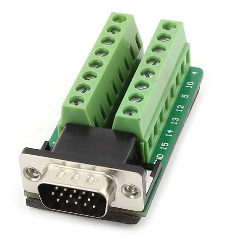
2. D-Subminiature (D-Sub) Connectors
D-Sub connectors are widely used for serial communication interfaces, such as RS-232, and for connecting computer peripherals. They have a trapezoidal shape and come in different sizes and pin counts.
Characteristics of D-Sub Connectors
- Available in various sizes (DB9, DB15, DB25, etc.)
- Robust and durable construction
- Suitable for high-density connections
- Can be male or female
Applications of D-Sub Connectors
- Serial communication interfaces (RS-232, RS-422, RS-485)
- VGA and DVI video connectors
- Industrial control systems
3. USB Connectors
USB (Universal Serial Bus) connectors are prevalent in consumer electronics and computer peripherals. They provide a standardized interface for data transfer and power supply.
Characteristics of USB Connectors
- Available in different versions (USB 1.0, 2.0, 3.0, 3.1, 4.0)
- Supports plug-and-play functionality
- Provides power and data over a single cable
- Reversible connector design (USB Type-C)
Applications of USB Connectors
- Computer peripherals (mice, keyboards, printers)
- Smartphone and tablet charging and data transfer
- External storage devices
4. Modular Connectors (RJ45, RJ11)
Modular connectors, such as RJ45 and RJ11, are commonly used for Ethernet and telephone connections respectively. They provide a standardized interface for communication networks.
Characteristics of Modular Connectors
- Compact and lightweight design
- Locking mechanism for secure connections
- Available in various categories (Cat5, Cat6, etc.)
- Can be shielded or unshielded
Applications of Modular Connectors
- Ethernet networks (RJ45)
- Telephone systems (RJ11)
- Industrial control systems
5. Power Connectors
Power connectors are used for supplying electrical power to PCBs. They come in various types, such as barrel connectors, terminal blocks, and Molex connectors.
Characteristics of Power Connectors
- Designed for high current capacity
- Available in different voltage ratings
- Can be panel-mounted or board-mounted
- Polarized to prevent incorrect connections
Applications of Power Connectors
- AC/DC power supplies
- Battery connections
- Industrial equipment
6. RF Connectors
RF (Radio Frequency) connectors are used for high-frequency signal transmission in wireless communication systems. They are designed to minimize signal loss and maintain signal integrity.
Characteristics of RF Connectors
- Available in various types (SMA, BNC, N, etc.)
- Designed for specific frequency ranges
- Impedance-matched to minimize signal reflections
- Can be straight or right-angled
Applications of RF Connectors
- Wireless communication systems
- Antennas and antenna arrays
- Test and measurement equipment
Connector Selection Considerations
When selecting PCB connectors for your project, consider the following factors:
-
Application Requirements: Determine the specific requirements of your application, such as data rate, power requirements, environmental conditions, and space constraints.
-
Connector Type: Choose the appropriate connector type based on the interface requirements, such as USB for data transfer or power connectors for power supply.
-
Pin Count and Pitch: Select connectors with the required number of pins and appropriate pitch (spacing between pins) to ensure compatibility with mating connectors and PCB layout.
-
Mounting Type: Consider whether through-hole or surface-mount connectors are more suitable for your PCB Assembly process and available space.
-
Durability and Reliability: Evaluate the durability and reliability requirements of your application. Consider factors such as mating cycles, vibration resistance, and environmental conditions.
-
Signal Integrity: For high-speed or high-frequency applications, choose connectors that minimize signal distortion and maintain signal integrity. Consider shielded connectors or those with impedance matching.
-
Cost and Availability: Balance the cost and availability of connectors with your project budget and production timeline. Consider lead times and minimum order quantities.

PCB Connector Comparison Table
| Connector Type | Characteristics | Applications |
|---|---|---|
| Header | Various pin counts and pitches, through-hole mounting | Board-to-board connections, prototyping |
| D-Sub | Trapezoidal shape, high-density connections | Serial communication, video interfaces |
| USB | Standardized interface, power and data over a single cable | Computer peripherals, smartphone charging |
| Modular (RJ45, RJ11) | Compact design, locking mechanism | Ethernet networks, telephone systems |
| Power | High current capacity, various voltage ratings | Power supplies, battery connections |
| RF | High-frequency signal transmission, impedance-matched | Wireless communication, antennas |

Frequently Asked Questions (FAQ)
-
What is the difference between through-hole and surface-mount connectors?
Through-hole connectors have pins that are inserted into holes drilled in the PCB and soldered on the opposite side. Surface-mount connectors have leads that are soldered directly onto the surface of the PCB. Surface-mount connectors offer a more compact footprint and are suitable for automated assembly processes. -
How do I choose the right connector for my application?
Consider factors such as the interface requirements (USB, Ethernet, power, etc.), pin count, pitch, mounting type, durability, signal integrity, and cost. Evaluate your specific application needs and select a connector that meets those requirements. -
Can I mix different types of connectors on the same PCB?
Yes, you can use different types of connectors on the same PCB, depending on your application requirements. For example, you can have a USB connector for data transfer, a power connector for power supply, and header connectors for board-to-board connections. -
What is the importance of connector orientation and keying?
Connector orientation and keying ensure that connectors are mated correctly and prevent accidental misalignment or reversed connections. Keyed connectors have a unique shape or notch that allows them to be inserted only in the correct orientation, preventing damage to the connector or the connected devices. -
How can I ensure the reliability of PCB connectors in harsh environments?
Select connectors that are rated for the specific environmental conditions your application will encounter, such as temperature range, humidity, vibration, and shock. Consider using connectors with robust construction, gold-plated contacts for corrosion resistance, and sealed or IP-rated housings for protection against dust and moisture ingress.

Conclusion
PCB connectors play a crucial role in establishing reliable electrical and mechanical connections between printed circuit boards and other devices. Understanding the different types of PCB connectors, their characteristics, and applications is essential for selecting the right connector for your project.
By considering factors such as interface requirements, pin count, mounting type, durability, signal integrity, and cost, you can make an informed decision when choosing PCB connectors. Whether you need board-to-board connections, data transfer interfaces, power supply connections, or high-frequency signal transmission, there is a suitable connector available to meet your specific needs.
By following best practices for connector selection and design, you can ensure reliable and robust connections in your electronic devices and systems. Always refer to manufacturer datasheets and application notes for detailed specifications and guidelines when working with PCB connectors.


Leave a Reply