What is a Diode?
A diode is a two-terminal electronic component that allows current to flow in one direction while blocking it in the opposite direction. It consists of a p-n junction, which is formed by joining a p-type semiconductor (positive) with an n-type semiconductor (negative). When the positive side (anode) is connected to a higher voltage than the negative side (cathode), the diode conducts current. Conversely, when the cathode is at a higher voltage than the anode, the diode blocks current flow.
Diodes are used in various applications, such as:
- Rectification: Converting alternating current (AC) to direct current (DC)
- Voltage regulation: Maintaining a constant voltage level
- Overvoltage protection: Preventing excessive voltage from damaging sensitive components
- Signal conditioning: Shaping and filtering electronic signals
Common Types of Diodes
There are several types of diodes, each designed for specific purposes. Some of the most common types include:
-
Rectifier Diodes: These diodes are used in power supply circuits to convert AC to DC. They are designed to handle high currents and voltages.
-
Zener Diodes: Zener diodes are used for voltage regulation. They maintain a constant voltage across their terminals when operated in reverse bias mode.
-
Light Emitting Diodes (LEDs): LEDs emit light when current flows through them. They are used in various applications, such as displays, indicators, and lighting.
-
Schottky Diodes: Schottky diodes have a lower forward voltage drop and faster switching speeds compared to regular diodes. They are often used in high-frequency applications.
-
Varactor Diodes: Varactor diodes have a variable capacitance that changes with the applied reverse bias voltage. They are used in tuning circuits and voltage-controlled oscillators.

Why Test a Diode?
Diodes can fail due to various reasons, such as:
- Excessive current or voltage stress
- Overheating
- Manufacturing defects
- Aging and wear
When a diode fails, it can either short circuit (allowing current to flow in both directions) or open circuit (blocking current flow entirely). In some cases, a diode may develop a high resistance, leading to a voltage drop across its terminals.
Testing a diode helps you determine whether it is functioning correctly or has failed. By identifying faulty diodes, you can troubleshoot and repair electronic circuits more effectively, saving time and resources.

Diode Testing Methods
There are several methods to test a diode, each with its advantages and limitations. The most common diode testing methods are:
1. Multimeter Testing
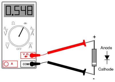
A multimeter is a versatile tool that can be used to test various electronic components, including diodes. Most digital multimeters have a dedicated diode test function, which applies a small forward voltage to the diode and measures the voltage drop across its terminals.
To test a diode using a multimeter:
- Set the multimeter to the diode test function (usually denoted by a diode symbol).
- Connect the red probe to the anode (positive terminal) and the black probe to the cathode (negative terminal) of the diode.
- Read the voltage drop displayed on the multimeter.
If the diode is functioning correctly, the multimeter should display a voltage drop between 0.5V and 0.8V for a silicon diode, or around 0.3V for a germanium diode. If the multimeter displays “OL” (open loop) or a very high resistance, the diode is likely open. If the multimeter displays a voltage drop close to 0V in both directions, the diode is likely shorted.
| Diode Type | Forward Voltage Drop |
|---|---|
| Silicon | 0.5V – 0.8V |
| Germanium | ~0.3V |
2. Ohmmeter Testing
An ohmmeter, which is often a part of a multimeter, can also be used to test a diode. This method involves measuring the resistance of the diode in both forward and reverse bias conditions.
To test a diode using an ohmmeter:
- Set the ohmmeter to the resistance measurement mode (usually denoted by the Ω symbol).
- Connect the red probe to the anode and the black probe to the cathode of the diode.
- Read the resistance value displayed on the ohmmeter.
- Reverse the probe connections and read the resistance value again.
A functional diode should display a low resistance (a few hundred ohms to a few kiloohms) in the forward bias condition and a very high resistance (several megohms) in the reverse bias condition. If the resistance is low in both directions, the diode is likely shorted. If the resistance is high in both directions, the diode is likely open.
| Diode Condition | Forward Bias Resistance | Reverse Bias Resistance |
|---|---|---|
| Functional | Low (100Ω – 10kΩ) | High (>1MΩ) |
| Shorted | Low (<10Ω) | Low (<10Ω) |
| Open | High (>1MΩ) | High (>1MΩ) |
3. Curve Tracer Testing
A curve tracer is a specialized instrument that plots the current-voltage (I-V) characteristic curve of a diode. This method provides a more comprehensive analysis of the diode’s performance, including its forward voltage drop, reverse breakdown voltage, and leakage current.
To test a diode using a curve tracer:
- Connect the diode to the curve tracer according to the manufacturer’s instructions.
- Set the voltage and current ranges appropriate for the diode being tested.
- Observe the I-V curve displayed on the curve tracer’s screen.
A functional diode should display a characteristic I-V curve, with a sharp knee at the forward voltage drop and a very low current in the reverse bias region. Any deviations from this curve, such as a high leakage current or a low breakdown voltage, indicate a faulty diode.
While curve tracer testing is more accurate and informative than multimeter or ohmmeter testing, it requires specialized equipment and may not be practical for quick checks or field testing.

Precautions and Safety Measures
When testing diodes, it is essential to follow these precautions and safety measures:
- Always disconnect power from the circuit before testing components.
- Use appropriate test equipment and follow the manufacturer’s instructions.
- Be cautious when handling high-voltage or high-current diodes, as they can cause electric shock or burns.
- Wear protective gear, such as safety glasses and insulated gloves, when working with hazardous voltages or currents.
- Ensure proper ventilation when working with components that may emit harmful fumes or particles.
Frequently Asked Questions (FAQ)
-
Q: Can a diode be tested in-circuit?
A: While it is possible to test a diode in-circuit, the results may not be accurate due to the influence of other components. It is best to remove the diode from the circuit for reliable testing. -
Q: How can I determine the polarity of an unmarked diode?
A: The cathode of a diode is usually marked with a band or stripe. If there are no markings, you can use a multimeter’s diode test function to identify the polarity. The multimeter will display a voltage drop when the red probe is connected to the anode and the black probe to the cathode. -
Q: Can a diode be damaged by excessive testing current?
A: Yes, applying excessive current to a diode during testing can damage the component. Always use the appropriate current range on your test equipment and follow the manufacturer’s specifications for the diode being tested. -
Q: How do I test a Zener diode?
A: To test a Zener diode, use a variable voltage source and a Current-Limiting Resistor in series with the diode. Gradually increase the voltage until the diode starts conducting in the reverse direction. The voltage at which this occurs should match the Zener diode’s specified breakdown voltage. -
Q: Can a faulty diode cause other components to fail?
A: Yes, a faulty diode can cause other components in the circuit to fail by allowing excessive current to flow or by not providing the necessary protection. It is essential to identify and replace faulty diodes promptly to prevent further damage to the circuit.
Conclusion
Testing diodes is a crucial skill for anyone working with electronic circuits. By using the appropriate methods and tools, such as a multimeter, ohmmeter, or curve tracer, you can quickly identify faulty diodes and troubleshoot circuit issues. Remember to follow safety precautions and guidelines when working with electronic components, and always double-check your results to ensure accurate diagnosis and repair.
By mastering the art of diode testing, you can save time, resources, and frustration when dealing with electronic projects or repairs. Whether you are a hobbyist or a professional, understanding how to test diodes is an invaluable skill that will serve you well in the world of electronics.


Leave a Reply