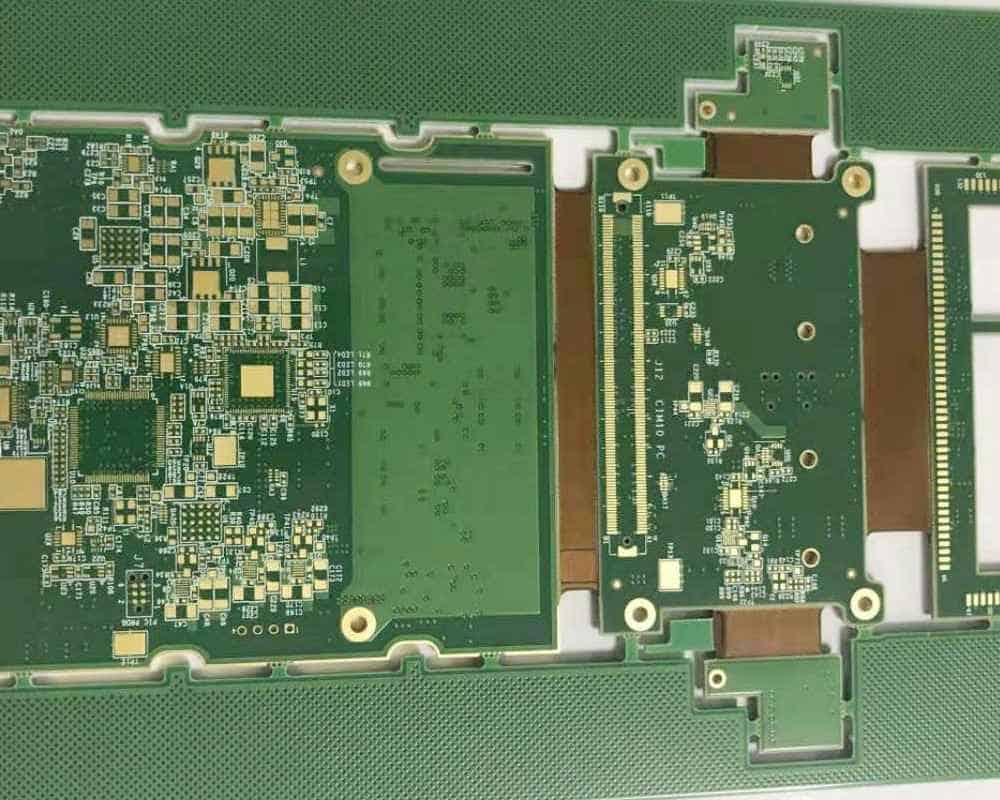
Altium offers robust tools for designing rigid-flex printed circuit boards (PCBs). Rigid-flex PCBs provide a versatile solution, combining the stability of a rigid PCB with the flexibility of a flex PCB. In this article, we will explore what makes Altium well-suited for rigid-flex design and some of the key applications that can benefit from this technology.
What is Rigid-Flex PCB Design?
A rigid-flex PCB consists of rigid sections interconnected by flexible sections. The rigid sections provide mechanical stability and the flexible sections allow dynamic flexing and bending. In a sense, rigid-flex combines the best attributes of rigid boards and flex boards.
Rigid-flex PCBs are ideal for applications that require:
- Dynamic flexing and bending
- Space and weight savings
- Enhanced reliability
- Three-dimensional design
Some of the industries and products that commonly use rigid-flex PCBs include aerospace, defense, medical, consumer electronics, and robotics.
The Benefits of Altium for Rigid-Flex Design
Altium provides dedicated tools for every stage of the rigid-flex design process:
Flexible board outline and layer stack creation – Easily define rigid and flex sections, layer stacks, cover layers, and bend areas.
2D and 3D rigid-flex modeling – Visualize the rigid-flex board in 2D and 3D including flex and bend areas.
Dynamic bend simulation – Simulate and analyze flexing and vibration modes. Identify potential areas of stress.
DFM verification and analysis – Validate manufacturability rules specific to rigid-flex fabrication. Model layer misregistration effects.
Transferring designs to manufacturing – Robust tools for generating comprehensive manufacturing outputs and documentation.
In summary, Altium allows PCB designers to efficiently model, analyze, verify, and document rigid-flex designs all within a unified design environment. The specialized rigid-flex features simplify what is often a very complex PCB technology.
Applications of Rigid-Flex PCBs

Rigid-flex PCBs open up new design possibilities in a range of products and industries. Here are some of the leading applications.
1. Medical Electronics
Medical devices like patient monitors, defibrillators, and imaging systems commonly leverage rigid-flex PCBs. Flexible sections allow the PCB to contour around the body or fit into tight spaces. This helps reduce device size and improve ergonomics. Rigid sections provide stability for more densely populated regions.
Specific examples include:
- Hearing aids
- Pacemakers
- Ultrasound transducers
- Endoscopes
- Wearable monitors
2. Consumer Electronics
Mobile consumer electronics benefit from rigid-flex PCBs in multiple ways. The flexible sections help:
- Reduce the overall device footprint by folding and wrapping the PCB
- Absorb mechanical stress and protect solder joints from cracking
- Enable moving display panels and hinged sections
Examples include smartphones, tablets, laptops, game systems, and VR headsets. Rigid-flex allows these devices to be more compact and robust.
3. Automotive Electronics
Vehicles utilize many complex electronic systems. Rigid-flex PCBs allow these systems to withstand vibration while routing across joints and through tight cabling channels. Example automotive applications include:
- ABS control units
- Transmission control modules
- Engine control units
- Body control modules
- Airbag deployment systems
4. Aerospace and Defense
The aerospace and defense industries commonly leverage rigid-flex PCBs for guidance systems, radars, communications, and other high reliability systems where space and weight are constrained. The dynamic flex capability allows the boards to move and adapt as needed.
Design Considerations
Here are some of the main considerations when working with rigid-flex PCBs:
Board layers – Determine the number of conductive layers required for both rigid and flex sections based on complexity and high-speed needs.
| Section | Typical Layers |
|---|---|
| Rigid sections | 2-20+ layers |
| Flex sections | 1-4 layers |
Conductive traces – Use narrower traces and spaces in the flex area to withstand bending stress. Wider traces are often used in the rigid sections.
Board thickness – Rigid sections are typically 0.062” or thicker. Flex sections are 0.008-0.015”. Special adhesives bond the sections together.
Flexible and rigid component placement – Position components accordingly and ensure terminations will withstand dynamic bending.
Flex folds – Define fold lines along the x and y axis and utilize rigid support structures if needed.
Material selection – Choose robust flexible substrate materials like polyimide that can handle repeated bending.
Fabrication and assembly – Work closely with manufacturers throughout the design process to ensure manufacturability.
FAQ

Here are answers to some frequently asked questions about rigid-flex PCB design with Altium:
What are the layer stack options for rigid-flex boards?
Altium provides complete flexibility (no pun intended) for defining layer stacks in rigid and flex sections. You can specify different layer counts in each section along with cover layers, bondply layers, and other stackup requirements.
How are components handled across rigid and flex sections?
You can assign components to either the rigid or flex section. Altium’s tools help manage clearances, spacing, and termination patterns for components on flex sections so they are not damaged during bending.
Can blind/buried vias be used in rigid-flex boards?
Yes, Altium fully supports blind and buried vias to transition between layer surfaces in rigid-flex designs, which helps minimize layer count. Microvias are also commonly used in the flex areas.
What fabrication outputs does Altium support?
Altium enables detailed documentation for rigid-flex manufacturing. In addition to standard fabrication and assembly files, you can generate reports focused on materials, special adhesives, and instructions for assembling and bonding the rigid-flex PCB.
How are thermal stresses analyzed in rigid-flex boards?
Altium allows you to model thermal expansion and contraction effects on traces and vias in the flex regions during dynamic bending simulations. This highlights potential areas of stress concentration.
In summary, Altium provides a complete set of tools optimized for the unique requirements of rigid-flex PCB design. The capability to model, analyze, and document complex rigid-flex boards helps take the guesswork out of the process. Whether you’re designing consumer devices, medical systems, aerospace electronics, or automotive applications, Altium has you covered for your rigid-flex design needs.


Leave a Reply