Introduction to the 1N4003 Diode
The 1N4003 diode is a popular and versatile rectifier diode widely used in various electronic applications. It is part of the 1N400x series of diodes, which are known for their reliability, affordability, and excellent performance in low-voltage, low-current applications. In this comprehensive guide, we will explore the features, specifications, and applications of the 1N4003 diode, helping you understand how to effectively utilize this component in your electronic projects.
What is a Rectifier Diode?
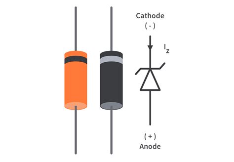
A rectifier diode is a semiconductor device that allows current to flow in only one direction, from its anode to its cathode. When the voltage at the anode is higher than the voltage at the cathode, the diode is forward-biased and conducts current. Conversely, when the voltage at the cathode is higher than the voltage at the anode, the diode is reverse-biased and blocks current flow.
Rectifier diodes are commonly used in power supply circuits to convert alternating current (AC) into direct current (DC). They are also used in various other applications, such as voltage clamping, voltage multipliers, and reverse polarity protection.
1N4003 Diode Specifications
To effectively use the 1N4003 diode in your projects, it is essential to understand its key specifications. The following table summarizes the main parameters of the 1N4003 diode:
| Parameter | Value |
|---|---|
| Peak Reverse Voltage (PRV) | 200 V |
| Average Forward Current (IF(AV)) | 1 A |
| Peak Forward Surge Current (IFSM) | 30 A |
| Maximum Forward Voltage (VF) | 1.1 V @ 1 A |
| Reverse Recovery Time (trr) | 3 µs |
| Operating Temperature Range | -65°C to 175°C |
Peak Reverse Voltage (PRV)
The peak reverse voltage (PRV) is the maximum voltage that the diode can withstand in the reverse-biased condition without experiencing breakdown. For the 1N4003 diode, the PRV is 200 V, which means it can safely block reverse voltages up to 200 V.
Average Forward Current (IF(AV))
The average forward current (IF(AV)) is the maximum continuous current that the diode can conduct in the forward direction without exceeding its thermal limits. The 1N4003 diode has an IF(AV) of 1 A, making it suitable for low-current applications.
Peak Forward Surge Current (IFSM)
The peak forward surge current (IFSM) is the maximum current that the diode can handle for a short duration, typically specified for a single half-cycle of a 60 Hz sine wave. The 1N4003 diode has an IFSM of 30 A, which allows it to withstand brief current spikes without damage.
Maximum Forward Voltage (VF)
The maximum forward voltage (VF) is the voltage drop across the diode when it is conducting its rated forward current. For the 1N4003 diode, the VF is 1.1 V at a forward current of 1 A. This relatively low forward voltage drop makes the 1N4003 diode efficient in low-voltage applications.
Reverse Recovery Time (trr)
The reverse recovery time (trr) is the time required for the diode to transition from the conducting state to the blocking state when the voltage across it rapidly changes from forward-biased to reverse-biased. The 1N4003 diode has a trr of 3 µs, which is suitable for most low-frequency applications.

Applications of the 1N4003 Diode
The 1N4003 diode finds use in a wide range of electronic applications due to its reliability, affordability, and performance. Some common applications include:
Power Supply Rectification
One of the most common applications of the 1N4003 diode is in power supply circuits for rectifying AC voltage into DC voltage. In a full-wave bridge rectifier configuration, four 1N4003 diodes can be used to convert AC input into pulsating DC output, which can then be smoothed using a capacitor to obtain a steady DC voltage.
Voltage Clamping
The 1N4003 diode can be used as a voltage clamping device to limit the voltage across a component or circuit to a specific value. By connecting the diode in parallel with the component, with its cathode connected to the positive voltage rail and its anode connected to the component, the diode will conduct and clamp the voltage across the component to the diode’s forward voltage drop when the voltage exceeds this value.
Reverse Polarity Protection
In circuits where the power supply polarity is critical, such as in battery-powered devices, the 1N4003 diode can be used to provide reverse polarity protection. By placing the diode in series with the power supply, with its anode connected to the positive terminal and its cathode connected to the load, the diode will block current flow if the power supply polarity is accidentally reversed, protecting the circuit from damage.
Flyback Diodes
In inductive load applications, such as relays and motors, the 1N4003 diode can be used as a flyback diode to suppress voltage spikes generated by the collapsing magnetic field when the load is switched off. By connecting the diode in parallel with the inductive load, with its cathode connected to the positive voltage rail and its anode connected to the load, the diode provides a path for the inductor’s current to flow when the supply voltage is removed, preventing high-voltage spikes that could damage other components in the circuit.

Comparing the 1N4003 Diode with Other 1N400x Series Diodes
The 1N400x series consists of several rectifier diodes with varying specifications, allowing designers to choose the most suitable diode for their specific application. The following table compares the key parameters of the 1N4001, 1N4002, 1N4003, 1N4004, 1N4005, 1N4006, and 1N4007 diodes:
| Parameter | 1N4001 | 1N4002 | 1N4003 | 1N4004 | 1N4005 | 1N4006 | 1N4007 |
|---|---|---|---|---|---|---|---|
| PRV (V) | 50 | 100 | 200 | 400 | 600 | 800 | 1000 |
| IF(AV) (A) | 1 | 1 | 1 | 1 | 1 | 1 | 1 |
| IFSM (A) | 30 | 30 | 30 | 30 | 30 | 30 | 30 |
| VF (V) | 1.1 | 1.1 | 1.1 | 1.1 | 1.1 | 1.1 | 1.1 |
As evident from the table, the main difference between the diodes in the 1N400x series lies in their peak reverse voltage (PRV) ratings. The 1N4003 diode, with its 200 V PRV, sits in the middle of the series, offering a balance between voltage handling capability and cost-effectiveness.

Proper Handling and Soldering of the 1N4003 Diode
To ensure optimal performance and reliability of the 1N4003 diode in your electronic projects, it is crucial to handle and solder the component correctly. Here are some guidelines to follow:
Electrostatic Discharge (ESD) Precautions
Like most semiconductor devices, the 1N4003 diode is susceptible to damage from electrostatic discharge (ESD). When handling the diode, always take proper ESD precautions, such as wearing an antistatic wrist strap or working on an ESD-safe mat. Avoid touching the leads of the diode directly, and store unused diodes in antistatic packaging.
Soldering Guidelines
When soldering the 1N4003 diode, follow these guidelines to prevent damage to the component:
- Use a temperature-controlled soldering iron with a suitable tip size for the diode’s lead diameter.
- Set the soldering iron temperature to around 300°C to 350°C (572°F to 662°F) for lead-free solder, or 250°C to 300°C (482°F to 572°F) for leaded solder.
- Apply heat to the lead and the pad simultaneously, ensuring that both are heated evenly.
- Introduce the solder to the joint, allowing it to flow around the lead and the pad. Avoid applying solder directly to the soldering iron tip.
- Keep the soldering time as short as possible, ideally less than 3 seconds, to prevent excessive heat from damaging the diode.
- Allow the joint to cool naturally; avoid using cooling agents or blowing on the joint.
Lead Forming and Bending
If you need to form or bend the leads of the 1N4003 diode to fit your circuit layout, use a pair of needle-nose pliers or a lead bending tool. Grip the lead close to the diode body to minimize stress on the component, and avoid bending the leads multiple times, as this can weaken the lead and cause it to break off.
Frequently Asked Questions (FAQ)
1. Can I use a 1N4003 diode in place of a 1N4001 or 1N4002 diode?
Yes, you can use a 1N4003 diode in place of a 1N4001 or 1N4002 diode, as the 1N4003 has a higher peak reverse voltage (PRV) rating. However, keep in mind that the 1N4003 diode may be slightly more expensive than the lower-rated diodes.
2. Can I use a 1N4003 diode for high-frequency applications?
The 1N4003 diode is designed primarily for low-frequency applications, such as power supply rectification and voltage clamping. For high-frequency applications, it is recommended to use diodes specifically designed for high-speed switching, such as Schottky diodes or fast recovery diodes.
3. How do I determine the proper diode rating for my application?
To determine the proper diode rating, consider the following factors:
- Peak reverse voltage (PRV): Choose a diode with a PRV rating higher than the maximum reverse voltage expected in your circuit.
- Average forward current (IF(AV)): Select a diode with an IF(AV) rating higher than the maximum continuous forward current in your application.
- Peak forward surge current (IFSM): Ensure that the diode’s IFSM rating is sufficient to handle any brief current spikes in your circuit.
4. Can I connect multiple 1N4003 diodes in parallel to increase the current handling capacity?
While connecting diodes in parallel can increase the overall current handling capacity, it is generally not recommended. Due to slight variations in the diodes’ forward voltage drops, one diode may conduct more current than the others, leading to uneven current sharing and potential overheating. If higher current handling is required, it is better to choose a single diode with a higher average forward current rating.
5. How do I test a 1N4003 diode to ensure it is functioning properly?
To test a 1N4003 diode, follow these steps:
- Set a digital multimeter (DMM) to the diode test mode.
- Connect the DMM’s red probe to the diode’s anode and the black probe to the cathode.
- The DMM should display a forward voltage drop between 0.6 V and 0.7 V for a silicon diode like the 1N4003.
- Reverse the probe connections, with the red probe on the cathode and the black probe on the anode.
- The DMM should display an open circuit (OL) or a very high resistance, indicating that the diode is blocking current in the reverse direction.
If the diode fails to meet these criteria, it may be damaged or faulty and should be replaced.
Conclusion
The 1N4003 diode is a versatile and reliable rectifier diode that finds use in a wide range of electronic applications, from power supply rectification to voltage clamping and reverse polarity protection. By understanding its specifications, applications, and proper handling techniques, you can effectively incorporate the 1N4003 diode into your electronic projects, ensuring optimal performance and reliability.
When selecting a diode for your application, consider factors such as the peak reverse voltage, average forward current, and peak forward surge current ratings, and choose a diode that meets or exceeds your circuit’s requirements. By following proper soldering and handling guidelines, you can ensure that your 1N4003 diodes will function as intended and provide long-lasting performance in your electronic designs.


Leave a Reply