Introduction to Yagi Antennas
Yagi antennas, also known as Yagi-Uda antennas, are directional antennas commonly used in radio communication, television broadcasting, and wireless networking. Named after its inventors, Shintaro Uda and Hidetsugu Yagi, this antenna type has gained popularity due to its high gain, directivity, and relatively simple design. In this article, we will delve into the design formula of Yagi antennas, explore their parasitic elements, and discuss various aspects of this versatile antenna type.
How Yagi Antennas Work
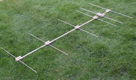
A Yagi antenna consists of three main components: a driven element, reflector, and one or more directors. The driven element is the part of the antenna that is directly connected to the transmitter or receiver. It is usually a half-wavelength dipole antenna. The reflector, located behind the driven element, is slightly longer than the driven element and helps to reflect the radio waves in the desired direction. The directors, positioned in front of the driven element, are slightly shorter than the driven element and help to focus the radio waves in the forward direction.
The arrangement of these elements creates a highly directional antenna that concentrates the radio waves in a specific direction, resulting in increased gain and reduced interference from unwanted signals.

Yagi Antenna Design Formula
To design a Yagi antenna, several factors need to be considered, including the operating frequency, the number of elements, and the spacing between the elements. The following is a step-by-step guide to designing a Yagi antenna:
Step 1: Determine the Operating Frequency
The first step in designing a Yagi antenna is to determine the operating frequency. This frequency will determine the wavelength of the radio waves and, consequently, the size of the antenna elements. The wavelength (λ) can be calculated using the following formula:
λ = c / f
Where:
– c is the speed of light (approximately 300,000,000 meters per second)
– f is the operating frequency in Hz
Step 2: Calculate the Element Lengths
Once the wavelength is known, the lengths of the driven element, reflector, and directors can be calculated using the following formulas:
- Driven Element Length (LDE) = 0.5 × λ
- Reflector Length (LR) = 0.495 × λ
- Director Length (LD) = 0.45 × λ
These lengths are approximate and may need to be adjusted based on the specific design requirements and the number of elements used.
Step 3: Determine the Element Spacing
The spacing between the elements plays a crucial role in the performance of the Yagi antenna. The optimal spacing depends on the number of elements and the operating frequency. A common rule of thumb is to space the elements at approximately 0.2 to 0.25 wavelengths apart.
For example, if the operating frequency is 144 MHz and the wavelength is 2.08 meters, the element spacing would be:
- Element Spacing = 0.2 × 2.08 = 0.416 meters (or approximately 41.6 cm)
Step 4: Calculate the Boom Length
The boom is the support structure that holds the antenna elements in place. Its length depends on the number of elements and the spacing between them. To calculate the boom length, use the following formula:
Boom Length = (Number of Elements – 1) × Element Spacing
For example, if the Yagi antenna has 6 elements and the element spacing is 0.416 meters, the boom length would be:
- Boom Length = (6 – 1) × 0.416 = 2.08 meters

Parasitic Elements in Yagi Antennas
Parasitic elements, namely the reflector and directors, play a vital role in shaping the radiation pattern and increasing the gain of a Yagi antenna. Let’s explore these elements in more detail:
Reflector
The reflector is positioned behind the driven element and is slightly longer than the driven element. Its primary function is to reflect the radio waves in the desired direction, thereby increasing the antenna’s gain and directivity. The reflector’s length is typically 5% longer than the driven element’s length.
Directors
Directors are placed in front of the driven element and are slightly shorter than the driven element. They help to focus the radio waves in the forward direction, further increasing the antenna’s gain and directivity. The number of directors used in a Yagi antenna can vary, with more directors generally resulting in higher gain and narrower beamwidth.
The length of each director is progressively shorter than the previous one, with the first director being approximately 5% shorter than the driven element. The length of subsequent directors decreases by about 2-3% per director.

Yagi Antenna Performance Characteristics
Yagi antennas offer several advantageous performance characteristics that make them popular for various applications. Some of these characteristics include:
Gain
Gain is a measure of how much the antenna increases the signal strength in the desired direction compared to a reference antenna, such as a dipole. Yagi antennas can achieve gains ranging from 6 dBi to over 20 dBi, depending on the number of elements and the design optimization.
Directivity
Directivity refers to the antenna’s ability to focus the radio waves in a specific direction. Yagi antennas are highly directive, with a narrow beamwidth that allows them to concentrate the signal power in the desired direction while rejecting signals from other directions. This characteristic helps to reduce interference and improve the signal-to-noise ratio.
Front-to-Back Ratio
The front-to-back ratio (F/B ratio) is the difference in signal strength between the front and back of the antenna. A high F/B ratio indicates that the antenna has good rejection of signals coming from the opposite direction of the main beam. Yagi antennas typically have F/B ratios ranging from 10 dB to 25 dB or more.
Bandwidth
Bandwidth refers to the range of frequencies over which the antenna can operate effectively. Yagi antennas have a relatively narrow bandwidth, typically around 2-3% of the center frequency. This means that they are designed to work efficiently within a specific frequency range and may require adjustments or modifications to operate at significantly different frequencies.
Applications of Yagi Antennas
Yagi antennas find applications in various fields, including:
-
Amateur Radio: Yagi antennas are widely used by amateur radio operators for long-distance communication on the HF, VHF, and UHF bands.
-
Television Broadcasting: Yagi antennas are commonly used for receiving over-the-air television signals, especially in areas with weak signal strength.
-
Wireless Networking: Yagi antennas can be used to extend the range of Wi-Fi networks, particularly in point-to-point links or for covering larger areas.
-
Radio Astronomy: Yagi antennas are employed in radio astronomy to detect and study celestial objects that emit radio waves.
-
Cellular Communication: Yagi antennas can be used as base station antennas in cellular networks to provide coverage in specific areas.
Frequently Asked Questions (FAQ)
-
Q: What is a Yagi antenna?
A: A Yagi antenna is a directional antenna that consists of a driven element, reflector, and one or more directors. It is designed to have high gain and directivity, making it suitable for long-distance communication and signal focusing. -
Q: How does a Yagi antenna work?
A: A Yagi antenna works by using parasitic elements (reflector and directors) to shape the radiation pattern and increase the gain in the desired direction. The driven element is the active part of the antenna, while the reflector and directors passively influence the radio waves. -
Q: What are the main components of a Yagi antenna?
A: The main components of a Yagi antenna are the driven element, reflector, and directors. The driven element is the active part connected to the transmitter or receiver, the reflector is placed behind the driven element to reflect the radio waves, and the directors are placed in front of the driven element to focus the waves in the forward direction. -
Q: How do I calculate the element lengths for a Yagi antenna?
A: To calculate the element lengths for a Yagi antenna, you need to know the operating frequency and wavelength. The driven element length is typically 0.5 × λ, the reflector length is 0.495 × λ, and the director length is 0.45 × λ, where λ is the wavelength. -
Q: Can I use a Yagi antenna for multiple frequencies?
A: Yagi antennas are designed to work efficiently within a specific frequency range, typically around 2-3% of the center frequency. While it is possible to use a Yagi antenna for multiple frequencies, its performance may degrade as you move away from the designed frequency. For optimal performance across different frequencies, you may need to adjust the element lengths or use separate antennas.
Conclusion
Yagi antennas have proven to be a reliable and efficient choice for directional radio communication across various applications. By understanding the design formula and the role of parasitic elements, you can create Yagi antennas that are tailored to your specific needs, whether it’s for amateur radio, television reception, or wireless networking.
Remember to consider factors such as the operating frequency, element lengths, spacing, and the number of elements when designing a Yagi antenna. By following the guidelines and formulas presented in this article, you can create high-performance antennas that provide excellent gain, directivity, and front-to-back ratio.
As with any antenna design, experimentation and fine-tuning may be necessary to achieve the best results. Don’t hesitate to adjust the element lengths or spacing based on your specific requirements and the performance you observe.
With a well-designed Yagi antenna, you can enjoy improved signal quality, reduced interference, and extended communication range, making it a valuable tool in your radio communication arsenal.


Leave a Reply