Introduction
Printed circuit boards (PCBs) are essential components in modern electronics that provide the mechanical structure and electrical connections for electronic components. While traditional rigid PCBs have served the electronics industry well, the emergence of smaller and more portable devices has driven the need for more flexible and space-saving PCB solutions.
Two of the most common types of flexible PCBs are flex PCBs and flexible printed circuits (FPCs). Both provide flexibility and space savings compared to rigid PCBs, but there are some key differences between the two technologies:
Flex PCBs
- Uses flexible but durable polyimide substrate material
- Can have portions that are rigid or flex
- Suitable for dynamic flexing applications
- More complex, multi-layer board constructions possible
- Components can be mounted directly to board
FPC
- Uses thin polyimide or polyester substrate
- Entire circuit is flexible
- Best for static or low frequency dynamic flexing
- Typically single or double-sided boards
- Connects to other PCBs using connectors
In this article, we will take a more in-depth look at flex PCB and FPC technologies and the main differences between them. We will compare their materials and construction, discuss their applications and use cases, and provide guidelines on when to use each technology.
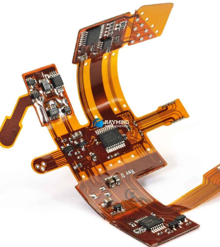
Flex PCB Construction and Materials
Flex PCBs get their flexible properties from the use of durable and bendable polyimide substrate materials. Polyimide provides excellent thermal stability and chemical resistance, which allows flex PCBs to maintain their mechanical and electrical integrity across a wide range of temperatures and operating conditions.
The most common thicknesses used for the polyimide substrate in flex PCBs range from 12.5 to 125 microns. The thinner material provides maximum flexibility while the thicker material offers better rigidity and component support where needed.
In terms of layer stackup, flex PCBs support complex multi-layer constructions, including:
- Single-sided
- Double-sided
- Multi-layer (up to 30+ layers possible)
Multi-layer flex PCBs sandwich alternating layers of copper and polyimide dielectric material, providing flexibility along with increased wiring density and routing options compared to double-sided boards.
Components can be directly soldered or adhesive mounted onto a flex PCB. Common component types include:
- Surface mount devices (SMDs)
- Chip-on-board mounting of ICs
- Connectors
- Switches, buttons, sensors
Stiffeners and covers can be added in selected areas of a flex PCB to provide enhanced rigidity and component support. This allows a single flex board design to have both rigid and dynamic flexing zones tailored to the application.
Flex PCB Construction
| Construction | Details |
|---|---|
| Substrate material | Polyimide (Kapton®) |
| Typical thickness range | 12.5 to 125 microns |
| Copper thickness | 8 to 35 microns |
| Common layer configurations | Single-sided, double-sided, multi-layer |
| Max layers | 30+ layers possible |
| Component mounting | Direct soldering and adhesive bonding |
| Stiffener/support | Can be added in rigid areas |
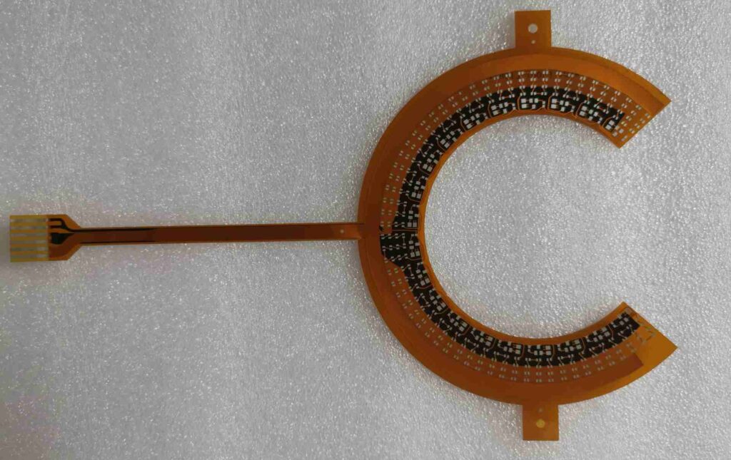
FPC Construction and Materials
In contrast to flex PCBs, FPCs use thinner and more flexible polyimide or polyester substrates, with typical thicknesses ranging from 6 to 51 microns. This allows FPCs to take on tighter bend radii than flex PCBs.
FPCs are limited to simpler single or double-sided constructions since the thinner dielectric materials are not well suited for multi-layer boards.
Components are not directly mounted on an FPC. Instead, connectors are used to join the FPC to a rigid PCB, which hosts the components. The components interface with the FPC through these connectors.
FPCs may have strategically placed stiffeners on areas that connect to rigid boards or components. This provides strength and stability to the connection points.
FPC Construction
| Construction | Details |
|---|---|
| Substrate material | Polyimide or polyester |
| Typical thickness range | 6 to 51 microns |
| Copper thickness | 8 to 35 microns |
| Layer configuration | Single or double-sided only |
| Max layers | 2 layers |
| Component mounting | None, uses connectors |
| Stiffener/support | At connectors |
In summary, FPC construction is simpler than flex PCBs, with thinner substrate material and no direct component mounting. This leads to excellent flexibility but at the cost of limited wiring density. The inclusion of connectors is required to interface FPCs with PCBs and components.
Flex PCB vs. FPC: Key Differences
Based on their construction and material differences, we can summarize some of the key distinctions between flex PCBs and FPCs:
| Parameter | Flex PCB | FPC |
|---|---|---|
| Substrate material | Polyimide | Polyimide or polyester |
| Substrate thickness | 12.5 to 125 μm | 6 to 51 μm |
| Max layers | 30+ | 1 or 2 |
| Component mounting | Direct | None, uses connectors |
| Dynamic flex capability | Moderate | Maximum |
| Static flex capability | Good | Excellent |
| Complexity | Medium to high | Low |
| Cost | Medium to high | Low |
To recap the major differences:
- Flexibility: FPCs can take tighter bends thanks to thinner material
- Complexity: Flex PCBs support more layers and routing complexity
- Component mounting: Only flex PCBs allow direct component attachment
- Dynamic flex: FPCs have maximum dynamic flex capability
- Static flex: FPCs excel in static and low frequency flex apps
- Cost: FPCs are lower cost due to simpler construction
With these key trait comparisons in mind, we can now better understand how these technologies are targeted towards different applications.
Flex PCB Applications
Flex PCBs provide a good balance between flexibility, complexity, and robustness. Here are some common applications:
Wearable Devices
Wearable devices such as smart watches, fitness bands, and health monitoring sensors can be made more comfortable and ergonomic by using flex PCBs. The dynamic flex capability allows the PCB to move smoothly with the user’s wrist or body. Direct component mounting also saves space.
Medical Devices
Medical devices often need to fit the contours of the human body. Flex PCBs allow devices like hearing aids and glucose monitors to have a curved shape that is less obtrusive to wear and operates reliably with body movements.
Consumer Electronics
Laptops, mobile phones, cameras, and other portable electronics utilize flex PCBs to interconnect rigid PCBs and route through hinged or constrained spaces. This saves volume over rigid PCBs.
Automotive Applications
Vehicles have many opportunities to employ flex PCBs, from dashboard display panels to engine control units. The boards can withstand vehicle vibration while routing through tight spaces.
Robotics
Humanoid and segmented robots need flex PCBs to facilitate motion across joints. The boards reliably transfer signals and power between rigid PCBs controlling each limb or actuator.
FPC Applications
FPCs are ideal when the utmost flexibility, low cost, and ease of routing are required:
Printers/Scanners
The printhead carriage in inkjet printers often uses an FPC. The thin flexible tail can accommodate the rapid back-and-forth motion across the paper width.
LCD Displays
Static flex FPCs nicely connect LCD or OLED displays to main rigid PCBs in devices like phones and tablets. The simple construction is low cost.
Wearables
Basic wearables like fitness bands may only need an inexpensive FPC. The FPC links to the main PCB while allowing the band to flex with the user.
Foldable Devices
Foldable phones and laptops use FPCs for their foldable displays and hinges. FPCs easily accommodate repeated bends along a fixed axis.
Computer Peripherals
FPCs work well for computer peripherals like keyboards and mice. An FPC can connect the peripherals’ internal board to the main computer.
Flex PCB vs FPC: How to Choose?
Here are some guidelines on when to choose a flex PCB versus an FPC for your application:
When to use a flex PCB:
- Dynamic or high frequency flexing motions required
- Direct component mounting needed on flexing portion
- Complex or multi-layer routing necessary
- Medium to high complexity circuitry
- Environmental protection required
- Long flex life (>100k cycles) needed
When to use an FPC:
- Static or low frequency flexing motion
- No components on flexing portion of circuit
- Simple routing with 1 or 2 conductive layers
- Low complexity circuitry
- Cost-sensitive application
- Short to medium flex life
Overall, consider flex PCB solutions when robustness, complexity, and durability are important. FPCs make more sense for simpler circuits in cost-sensitive applications requiring maximum static flexibility.
Conclusion
Flex PCBs and FPCs both provide useful solutions for integrating flexibility into electronic devices. While they share some similarities, core differences in materials, construction, complexity, and applications exist:
- Flex PCBs use thicker polyimide material to achieve a good balance of bendability and robustness, whereas FPCs maximize flexibility through very thin polymer films.
- Flex PCB construction supports more complex multi-layer circuits and direct component mounting, while FPCs are limited to simpler single or double-sided designs with only connectors for components.
- For dynamic flexing applications with demanding complexity and reliability requirements, flex PCBs are generally the better choice. FPCs are more cost-effective when simple routing and static flexibility are sufficient.
By understanding these key differences in capabilities, designers can make informed decisions when selecting between flex PCB or FPC implementations. Both technologies continue to progress, providing indispensable flexibility and reliability to the electronics that power our modern world.
FAQ
What are some key benefits of using a flex PCB?
Some benefits of using a flex PCB include:
- Dynamic flex capability for bendable/movable products
- Direct component mounting saves space
- Multi-layer constructions allow complex routing
- Withstands vibrations and frequent movements
- Can integrate rigid and flex zones as needed
What are some key benefits of using an FPC?
Benefits of using an FPC include:
- Extremely thin and lightweight
- Tight bend radii capability
- Low-cost, simple construction
- Easy to manually manipulate and route through spaces
- Good for static or low frequency dynamic flexing
Can you mount components directly onto an FPC?
No, components are not directly mounted onto an FPC. FPCs use connectors to interface with a rigid PCB, which hosts the components. The thin flexible material of an FPC is not well suited for component soldering.
How many flex cycles can a typical FPC withstand?
A typical FPC can withstand around 10,000 to 30,000 flexing cycles before failure. FPCs emphasize extreme flexibility over robustness. Flex PCBs, with their thicker substrates, can endure over 100,000 cycles in many cases.
Are FPCs less expensive than flex PCBs?
Yes, FPCs are generally less expensive than flex PCBs. The simpler single or double-sided constructions use less material. FPCs also avoid the cost of soldered components. The flex PCB’s more robust build quality comes at a higher price.


Leave a Reply