Introduction
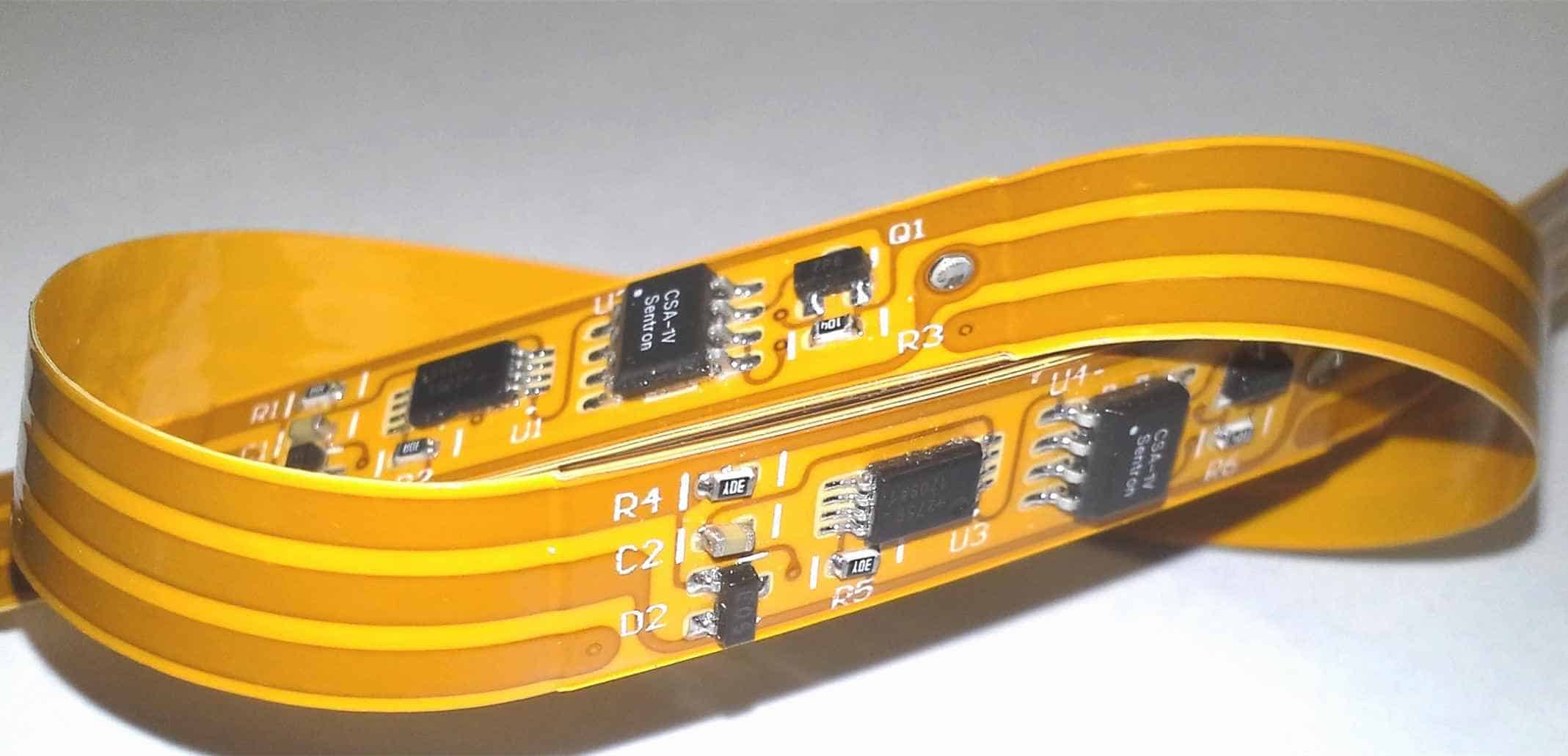
Printed circuit boards (PCBs) are essential components in electronics that provide mechanical support and electrical connections between electronic components. As technology advances, devices are getting smaller and require more flexible and compact PCB solutions. This has led to the development of flexible PCBs, which can bend and flex. The two main types of flexible PCBs are flex PCBs and flexible printed circuits (FPCs). Both provide flexibility but have some differences in their design, construction, and applications. This article will compare flex PCBs and FPCs in terms of their materials, construction, features, advantages and limitations, and typical applications.
Materials Used
The base material is the main difference between flex PCBs and FPCs.
Flex PCB Materials
- Polyimide: This is the most common base material for flex PCBs. Polyimide film provides flexibility, heat resistance, and chemical resistance. Common polyimide films include Kapton from DuPont and Apical from Kaneka.
- Polyester: More affordable but less heat resistant than polyimide. Common polyester films include Mylar from DuPont.
- Polyethylene naphthalate (PEN): Provides better thermal resistance than polyester. PEN films like Teonex from DuPont are used.
FPC Materials
- Polyester: The most common FPC base material. Provides more flexibility than traditional FR-4 rigid PCBs.
- Polyimide: Can be used but is more expensive than polyester. Offers higher temperature resistance.
Table comparing flex PCB and FPC base materials:
| Base Material | Flex PCB | FPC |
|---|---|---|
| Polyimide | Commonly used | Less common |
| Polyester | Less common | Most common |
| PEN | Used for high-temp | Not typically used |
Construction and Layers
Flex PCBs have a more complex construction with more layers, while FPCs have a simpler single or double layer design.
Flex PCB Construction
- Multiple conductive layers: Flex PCBs typically have 2 to 12 conductive copper layers separated by flexible dielectric material. Multiple layers allow for more complex circuitry.
- Adhesive layers: Adhesive is used to bond the layers together while maintaining flexibility. Common adhesive films are acrylic, epoxy, or nitrile phenolic.
- Cover layers: A coverlay (solder mask) and outline are added to the outer layers for protection and insulation. Common coverlay materials are acrylic, polyimide, epoxy, polyester.
- Stiffeners: Areas can be stiffened with materials like aluminum, steel, FR-4, or polyimide. Stiffeners provide strengthened mounting points.
FPC Construction
- 1-2 conductive layers: FPCs have just one or two conductive layers, limiting circuit complexity compared to flex PCBs.
- Adhesive layer: Some FPCs have an adhesive layer between two conductive layers.
- Cover layer: A coverlay is added to the outer layer for insulation and protection.
Table comparing flex PCB and FPC construction:
| Construction | Flex PCB | FPC |
|---|---|---|
| Conductive layers | 2-12 layers | 1-2 layers |
| Adhesive layers | Used between layers | Optional |
| Cover layers | Added to outer layers | Added to outer layer |
| Stiffeners | Added for strength | Not used |
Features and Capabilities
Due to their more complex multilayer design, flex PCBs offer more robust features and capabilities compared to FPCs.
Flex PCB Features
- Small vias and traces: More layers allow for smaller, high-density traces and vias. This enables more interconnects in a small space.
- Fine line resolution: Typical line width and spacing is ±0.05 mm (2 mils) with some up to ±0.025 mm (1 mil). Allows for miniaturization.
- Mixed embedded passives/actives: Passive components like resistors and capacitors can be screen printed between layers. Active components can also be embedded.
- High layer count: Up to 30 conductive layers are possible, enabling highly complex circuitry.
- Flex-rigid capability: Rigid FR-4 PCB sections can be integrated with the flex PCB areas for strength and component mounting.
FPC Features
- Less layers: Maximum 2 conductive layers limits the circuit complexity compared to flex PCBs.
- Larger traces: Typical minimum trace is 0.1 mm (4 mils) width and space. Larger than fine line flex PCB traces.
- Mainly passive interconnection: No embedded passives or actives. Mainly used for interconnections between PCBs.
- Low layer count: Only single or double layer options with no flex-rigid capability.
Table of features comparison:
| Feature | Flex PCB | FPC |
|---|---|---|
| Minimum trace size | ±0.025 mm | ±0.1 mm |
| Embedded passives/actives | Yes | No |
| Layer count | Up to 30 | 1-2 layers |
| Flex-rigid capability | Yes | No |
Advantages and Disadvantages
Flex PCB Advantages
- High circuit density with small components and traces.
- Complex multilayer circuits possible.
- Integrated passives/actives for miniaturization.
- Flex-rigid capability.
- Durable construction.
Flex PCB Disadvantages
- High startup and production costs.
- Longer fabrication time.
- Requires advanced specialized equipment.
FPC Advantages
- Low cost, fast fabrication.
- Simple construction with fewer process steps.
- Flexible and lightweight.
FPC Disadvantages
- Limited to simple single/double layer circuits.
- Larger minimum trace sizes.
- No embedded components or flex-rigid capability.
Table summarizing advantages and disadvantages:
| Flex PCB | FPC | |
|---|---|---|
| Advantages | High density circuits<br>Complex multilayer<br>Embedded components<br>Flex-rigid capability<br>Durable | Low cost<br>Fast fabrication <br>Simple construction<br>Lightweight and flexible |
| Disadvantages | High cost<br>Long fabrication<br>Advanced specialized equipment | Limited circuits<br>Larger traces<br>No embedded components<br>No flex-rigid |
Typical Applications
Due to their differing capabilities, flex PCBs and FPCs are used in different applications.
Flex PCB Applications
Complex and dense flex PCBs are well suited for:
- Consumer electronics like laptops, mobile phones, wearables, VR headsets
- Medical devices
- Industrial electronics in factory automation and control systems
- Aerospace and military electronics where reliability is critical
- Automotive electronics
FPC Applications
With their flexibility, simplicity and low cost, FPCs are commonly used for:
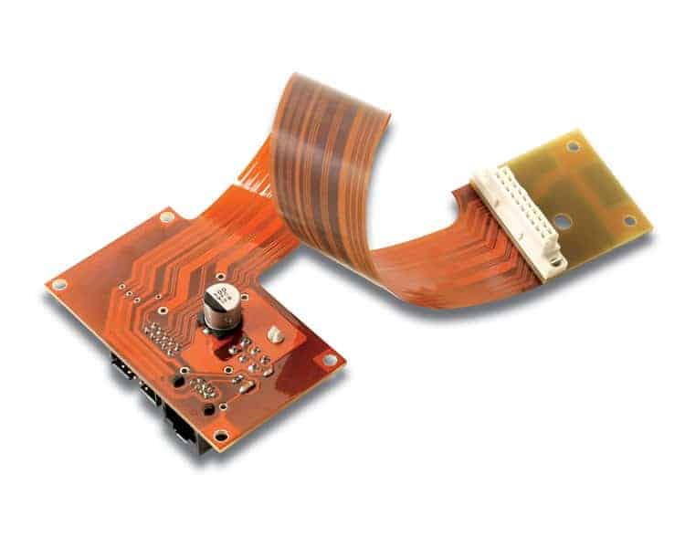
- Interconnections between rigid PCBs like in printers, optical drives, appliances.
- Internal connections in laptops, mobile phones.
- Wearable devices.
- LCD displays.
- Consumer electronics requiring simple connections.
Table summarizing typical applications:
| Application | Flex PCB | FPC |
|---|---|---|
| Consumer electronics | Advanced flex PCBs for complex, miniaturized devices | Simple FPCs for interconnections |
| Medical | Flex PCBs for compact, reliable circuitry | Some simple FPCs |
| Industrial/Automotive | Flex PCBs for durable, reliable electronics | Some simple FPC interconnections |
| Aerospace/Military | Flex PCBs for reliable, rugged electronics | Limited use |
Summary and Recommendations
- Flex PCBs offer multilayer circuitry with small components and traces enabling compact, complex electronics. FPCs are simpler with 1-2 layers for basic interconnections.
- For advanced electronics needing dense, reliable circuitry choose flex PCBs. For simpler interconnections select FPCs.
- Consider the application requirements. Flex PCBs suit advanced miniaturized devices. FPCs fit cost-sensitive simple connections.
- Work with a manufacturer experienced in flex PCBs/FPCs. Get their advice on selecting the best option for your application.
FQA
What are some key differences between flex PCBs and FPCs?
Some key differences are:
- Flex PCBs have 2-12 conductive layers while FPCs are limited to 1-2 layers. This enables more complex circuits with flex PCBs.
- Flex PCB minimum trace widths can be ±0.025 mm enabling high density. FPC minimum traces are ±0.1 mm.
- Flex PCBs allow embedded passives/actives. FPCs are mainly used for interconnections.
- Flex PCBs can integrate rigid sections but FPCs cannot.
Why choose a flex PCB over an FPC?
The main reasons to choose a flex PCB over an FPC are:
- You need a multilayer circuit with small, high-density traces and components. This allows complex, compact electronics.
- You want to embed passive components like resistors and capacitors or even active components. This further miniaturizes the design.
- You require sections of rigid PCB integrated with the flexible PCB for component mounting and strength.
- Your application is mission-critical requiring extremely reliable circuitry. The robust construction of flex PCBs is advantageous.
What are the main applications suitable for FPCs?
Some main applications suitable for FPCs include:
- Interconnections between rigid PCBs inside electronic devices like printers, laptops, and appliances.
- Internal connections inside mobile phones, wearable devices, display screens.
- Consumer electronics where low cost and simplicity are priorities.
- Applications requiring only 1 or 2 conductive layers.
FPCs work best in cost-sensitive applications where flexible simple connections between PCBs are needed. They are not suitable for complex multilayer circuits requiring high reliability.
What should you look for in a flex PCB/FPC manufacturer?
Important capabilities to look for in a manufacturer include:
- Experience and expertise with flex PCB and FPC technologies. Look for years in business and volume production.
- Adequate flex PCB/FPC specific equipment such as photolithography processes. Manual etching processes are unsuitable.
- Supply chain capabilities for sourcing high quality base materials and adhesives.
- Comprehensive quality control and testing.
- Prototyping abilities in addition to volume production.
- Design support and engineering review capabilities.
Choose a manufacturer focused on flex PCBs/FPCs rather than a general PCB shop. Their expertise and process knowledge are critical.
What information should you provide to a manufacturer when requesting a flex PCB/FPC quote?
Essential details to provide for an accurate quote include:
- PCB materials such as polyimide or polyester film type.
- Board dimensions (length, width, thickness).
- Number of flex and rigid layers.
- Minimum trace/space width.
- Copper thickness and finished copper weight.
- Stiffener material if required.
- Special coatings such as coverlay type.
- Quantity required.
- Any special requirements like controlled impedance, embedded components, etc.
Providing the manufacturer full specifications upfront allows them to accurately determine costs and production feasibility. This avoids surprises later.


Leave a Reply