Introduction
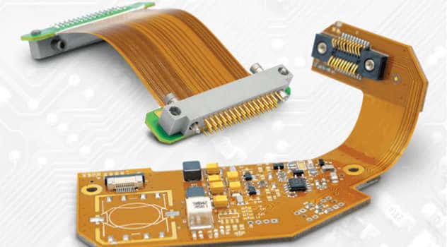
A flex PCB, also known as a flexible printed circuit board, is a type of printed circuit board made of flexible base material such as polyimide or polyester. Flex PCBs can be bent, folded, and twisted to fit into tight or mobile spaces in electronic devices. They are commonly used in consumer electronics, medical devices, automotive electronics, and aerospace applications that require flexible and dynamic connections.
The base material is a critical component that determines the overall flexility, durability, and performance of the flex PCB. As technology advances, new base materials are being developed to meet increasingly complex requirements. This article will provide an in-depth look at the different types of base materials used in flex PCBs and their properties and applications.
Common Base Materials for Flex PCBs
There are several widely used base materials for manufacturing flex PCBs:
Polyimide
Polyimide is the most common base material used in flex PCBs. The two main types of polyimide used are:
- Kapton: Kapton polyimide was developed by DuPont and offers a high degree of thermal stability and chemical resistance. It has excellent mechanical properties with high tensile strength and can withstand repeated bending. Kapton has good dielectric properties and is UL-94 V0 rated for flammability.
- Apical: An alternative polyimide that is more economical than Kapton but with comparable properties. Apical polyimide films are available in various thicknesses down to 12.5 microns.
Some key properties of polyimide base materials:
- High heat resistance of up to 400°C
- Good chemical resistance
- Excellent mechanical strength and flexibility
- Low dielectric constant and loss for stable electrical performance
- Good dimensional stability over a wide temperature range
Polyimide is most suitable for dynamic flex applications with tight bend radii and repeated flexing. Common applications include wearable devices, flex antennas, and complex flexible interconnections.
Polyester
Polyester, usually PET (polyethylene terephthalate), is lower cost alternative base material. It has the following properties:
- Moderate flexibility and bend radius
- Lower maximum operating temperature of around 125°C
- Higher dielectric constant than polyimide
- Susceptible to hydrolysis in high humidity environments
- UL-94 VTM-0 rated for flammability
Polyester flex PCBs can have cover layers bonded to the base film to improve chemical resistance. They are a lower cost option suitable for less demanding flexible circuits in consumer electronics and other applications not requiring very tight bends.
LCP (Liquid Crystal Polymer)
LCP is an advanced flex PCB substrate with extremely high heat resistance. Key features of LCP include:
- Exceptionally high melting point of over 280°C
- Stable electrical properties at high temperatures
- Low moisture absorption and excellent chemical resistance
- Superior dimensional stability under temperature fluctuations
- Low dielectric loss and high frequency signal integrity
- UL-94 V-0 flammability rating
The high heat tolerance makes LCP suitable for flex PCBs used in extreme environments such as automotive, aerospace, oil/gas drilling, and military systems. The high cost of LCP limits its use to specialized applications requiring the performance advantages.
PEN (Polyethylene Naphthalate)
PEN is a relatively new entrant as a high-performance flex PCB base material. It offers a unique set of properties:
- High temperature resistance of up to 180°C
- Extremely low moisture absorption, on par with LCP
- Good mechanical strength and flexibility
- Low dielectric constant and loss
- Better lower temperature performance than LCP
PEN provides an alternative to LCP for advanced flex applications requiring robust performance under wide temperature ranges. It has good potential for usage in automotive electronics and other dynamic flex applications.
Key Properties of Flex PCB Base Materials
Some of the important properties to consider when selecting a flex PCB base material are:
Flexibility – The bend radius dictates the minimum radius a flex PCB can be bent without damage. Lower bend radius means tighter folds are possible.
Heat resistance – The maximum operating temperature the material can withstand without degrading.
Chemical resistance – Ability to withstand exposure to different chemical products and environments.
Hydrolysis resistance – Measures water absorption which can compromise dielectric properties. Low is better.
Flammability rating – Materials are rated for flammability to UL-94 standards, with V-0 and VTM-0 being less flammable.
Dielectric constant – Affects signal integrity and impedance control at higher frequencies. Lower is better.
Coefficient of thermal expansion (CTE) – Indicates dimensional stability over temperature changes. Similar CTE to copper conductors is desired.
Mechanical properties – Important factors like tensile strength, elongation, and elastic modulus determine flex durability.
Here is a comparison table highlighting key properties for common flex PCB base materials:
| Property | Polyimide | Polyester | LCP | PEN |
|---|---|---|---|---|
| Bend Radius | 0.025mm | 0.10mm | 0.13mm | 0.05mm |
| Max Temperature | 400°C | 125°C | 280°C+ | 180°C |
| Dielectric Constant | 3.4 | 4.7 | 3.0 | 3.0 |
| Loss Tangent | 0.002 | 0.02 | 0.003 | 0.005 |
| CTE (ppm) | 20 | 18 | 17 | 20 |
| Moisture Absorption (%) | 2.5 | 0.15 | 0.04 | 0.02 |
| Flammability | V-0 | VTM-0 | V-0 | V-0 |
Manufacturing Process of Flex PCBs
Understanding the manufacturing process provides further insight into the flex PCB base material properties and requirements. The typical steps are:
- The flexible copper clad laminate is fabricated by bonding the base film to a thin layer of copper foil. Polyimide and polyester are the common films used.
- Photolithography is used to print the desired circuit pattern onto the copper layers. The unneeded copper is etched away leaving only the circuit traces.
- Components are assembled onto the surface using soldering or conductive epoxy adhesive. Automated pick and place machines are commonly used.
- To protect the circuits, a cover layer or “coverlay” made of the base film material is often laminated over the top and bottom surfaces. This encases the conductors.
- Contact holes are made in the coverlay to expose solder pads and probe test points. Flex PCBs are electrically tested.
- Rigid sections with standard FR-4 PCB may be incorporated onto the flex PCB for connectors or added components.
- The finished flex PCB is cut to size using precision lasers or punching. Electrical tests are performed again.
- Some flex PCBs are cleaned then coated with protective epoxy or parylene films per end customer requirements.
The base material must withstand the lamination pressures and temperatures which exceed 300°F. And the material must maintain integrity through the repeated flexing and handling steps of component assembly. This necessitates properties like high elongation and mechanical strength.
Applications and Examples
Flex PCBs are found in many types of electronic devices and products. Here are some examples of their use:
Medical:
- Portable patient monitors
- Ultrasound transducers and probes
- Hearing aids
- Wearable health monitors
Automotive:
- Engine control modules
- Anti-lock brake systems
- Transmission and throttle controls
- Sensor interconnects
Aerospace/Military:
- Guidance systems
- Avionics and flight controls
- Radar and antenna arrays
- Missile and rocket components
Consumer Electronics:
- Cellphones and smartphones
- Digital cameras
- Laptop and tablet computers
- Wearable technology
Industrial:
- Robotics
- Programmable logic controllers
- Power electronics
Other Applications:
- Flex antennas
- Solar products
- Instrumentation and test equipment
Some specific examples of flex PCB implementations include:
- Kapton flex PCB used in laptop hinge to connect screen to motherboard. Withstands continuous flexing cycles.
- Multi-layer LCP flex circuit boards in fighter jet phased array radar systems due to high temperature rating.
- Flexible polyimide display driver PCBs that connect to OLED panels in curved smart watches.
- Flexible heater circuits using polyester base material to wrap around industrial pipes for freeze protection.
Flex PCB versus Rigid-Flex PCBs
Rigid-flex PCBs are a hybrid technology that combines rigid FR-4 boards with flexible circuits. This allows high component density and complex interconnections combining both flexible and rigid sections in one assembly.
The rigid portions provide mechanical support and often house surface mount components or connectors. Flexible “jumpers” are used to interconnect between rigid areas and provide dynamic flexing capability where needed.
Polyimide is typically used for the flex layers due to superior flex properties. FR-4 with high Tg (glass transition temperature) is used for the thicker rigid sections. Adhesive layers bond the materials into a multilayer configuration.
Rigid-flex PCBs are ideal solutions for products like foldable mobile devices and military systems packed into tight aerodynamic profiles. The technology provides ultimate design flexibility to optimize the placement of components, routing, and dynamic flexure regions.
Factors in Selecting Flex PCB Base Materials
Choosing the right base material is an important decision when designing a flex PCB. Here are some of the considerations when making this selection:
- Required flexibility – How tight are the bend radii? Polyimide supports the smallest folds.
- Operating temperature range – Wide temperature range favors LCP or PEN over polyester.
- Cost constraints – Polyester and polyimide are lower cost; LCP and PEN are premium.
- Dielectric properties – High frequencies and impedance control favor LCP.
- Chemical resistance – Polyimide has the best resistance to most chemicals.
- Hydrolysis resistance – LCP and PEN have lowest moisture absorption.
- Mechanical robustness – Are high strength and ductility needed?
- Thermal endurance – How many temperature cycles will the flex PCB endure?
- Flammability rating – Are UL-94 V-0 or VTM-0 ratings required?
The target application will determine which of these parameters are most important to optimize. Consulting with experienced flex PCB manufacturers is recommended when selecting materials.
Future Trends for Flex PCB Base Materials
Advancements in base materials continue, driven by increasing demands for flex PCB performance. Some emerging trends include:
- Lower curing temperatures – Allows use of thinner flexible films to enable tighter bends.
- Improved CTE matching – Minimizes thermal stresses between conductors and dielectric.
- Higher frequency, lower loss – Supports high speed data transmission for 5G and beyond.
- Higher thermal conductivity – Improves heat dissipation in high power flex circuits.
- Bio-compatible materials – For use in medical implants and wearable devices.
- Lower moisture absorption – For robustness in challenging environments.
- Flame retardant properties – To meet expanding safety standards for flammability.
- Higher fracture toughness – For enhanced mechanical durability and flex life.
- Nano-engineered films – Thinner films with improved properties by leveraging nanotechnology.
Many exciting innovations in materials science will shape the future landscape of flexible PCB substrate materials and performance.
Conclusion
Flexible PCBs rely on specialized base materials that provide the necessary electrical, mechanical, and thermal properties to function in their demanding applications across electronics industries. Polyimide is the most prevalent for cost-effective general flex circuits, but new high-performance polymers like LCP and PEN enable flex PCBs to be used in extreme conditions. The base film must balance flexibility, heat resistance, chemical stability, dielectric performance, and manufacturability. Trends are pushing toward thinner, stronger and more reliable flexible PCB materials.
FAQs
What are some key differences between polyimide and polyester base materials?
Polyimide offers superior heat resistance, chemical resistance, mechanical strength and lower dielectric constant compared to polyester. Polyester costs less but has lower performance limits on temperature, chemical exposure, and bend radius.
Does flex PCB thickness affect the choice of base material?
Thinner flex PCBs generally require base films with higher mechanical strength and fracture toughness. Polyimide and LCP are suitable for very thin flex below 0.05mm. Thick flex above 0.2mm can utilize a wider range of materials.
Can you solder components directly onto flexible PCB substrates?
Most flex PCBs have a polyimide cover layer over the base substrate that withstands soldering temperatures. But the underlying flexible base material typically cannot sustain direct soldering without damage. Soldering is done onto solder pads on the outer circuit layers.
How are components attached to flexible PCBs?
For surface mount components, solder paste and reflow is commonly used, especially for higher density designs. Through-hole components are attached with conductive epoxy. Press-fit or crimped connectors can also be used.
Does flex PCB thickness affect flexibility and bend radius?
Yes, thinner flex PCBs can generally bend to a tighter radius. The thickness of the conductive copper layers is also a factor. Typical bend radii range from 2-3X the total PCB thickness.


Leave a Reply