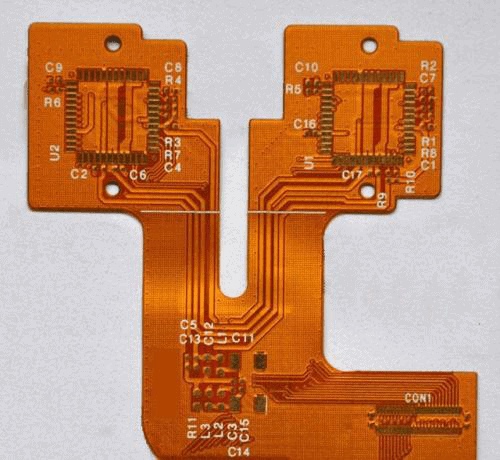
A Rogers PCB is a printed circuit board made using high frequency, high performance laminate materials manufactured by Rogers Corporation. Rogers laminates are commonly used in radio frequency (RF), microwave and other specialized high speed or high frequency applications that require tightly controlled electrical properties.
Some key aspects of Rogers PCBs include:
Rogers Laminate Materials
Rogers offers a wide range of circuit board substrate materials engineered for high frequency applications from HF to millimeter wave frequencies. Some popular laminate types include:
- RO4350B – Glass microfiber reinforced hydrocarbon ceramic. Used in RADAR, communications, aerospace.
- RT/duroid 6002 – Ceramic filled PTFE composite. Low loss, stable dielectric.
- RO4003C – Woven glass reinforced hydrocarbon ceramic. Common for cellular, WiFi, automotive.
- RT/duroid 5880 – PTFE composite with microfiber glass. Low loss, tight tolerance.
Key properties optimized for high frequency performance:
- Stable dielectric constant over frequency
- Low dissipation factor (loss tangent)
- Controlled dielectric thickness
- Excellent dimensional stability
- Low coefficient of thermal expansion
This provides consistent electrical performance across operating temperature range.
Benefits of Rogers PCBs
Some major benefits of using Rogers laminates for PCB fabrication include:
- Stable dielectric constant – Consistent electrical properties under varying conditions.
- Low loss – Less signal loss from dielectric absorption compared to FR-4.
- Tight impedance control – Precision manufacturing enables tight trace impedances.
- High frequency support – Materials optimized for HF, VHF, UHF applications.
- Excellent thermal performance – Efficient heat dissipation.
- High reliability – Materials resist absorption of moisture and contaminants.
- Flexible thickness – Available from 0.001″ to 0.062″ thick laminates.
These characteristics make Rogers substrates well-suited for advanced RF and microwave circuits with exacting electrical requirements.
Rogers vs. FR-4 PCBs
Rogers laminates differ significantly from standard FR-4 circuit boards. Some key differences:
| Parameter | Rogers PCB | FR-4 PCB |
|---|---|---|
| Dielectric Constant | 2.2 to 10.2 | 4.2 to 4.8 |
| Loss Tangent | 0.0009 to 0.002 | 0.015 to 0.025 |
| Z-axis CTE | 30 to 100 ppm/°C | 140 to 180 ppm/°C |
| Moisture Absorption | <0.2% | 0.2 to 0.4% |
| HF Signal Loss | Lower | Higher |
| Impedance Control | Much tighter | Looser |
| Thermal Conductivity | Higher | Lower |
| Cost | More expensive | Less expensive |
The superior electrical and thermal performance of Rogers laminates enables them to meet stringent requirements of RF and microwave circuits.
Rogers PCB Material Selection
With the wide range of substrate materials offered by Rogers, the optimal material depends on factors like:
- Operating frequency – Different dielectric constants suited for HF, VHF, UHF, microwave.
- Loss requirements – Applications like antennas need ultra-low loss.
- Impedance tolerance – Tight control for RF circuits, looser okay for digital logic.
- Temperature range – Some materials handle extreme temps better.
- Size constraints – Thinner laminates for tight spaces.
- Budget – Cost increasing with performance level.
- Lead time – Some materials have longer fabrication lead times.
Working with an experienced PCB manufacturer is recommended to analyze electrical and mechanical requirements to select the best laminate material for each application.

Rogers PCB Fabrication
Rogers PCB fabrication involves specialized processes tailored to high frequency applications. Some considerations include:
Layer Stackup
Need proper layer thicknesses, materials and sequence to achieve target impedance, coupling, etc. More complex than standard multilayer boards.
Dielectrics
Precise control of dielectric thicknesses with tight tolerances. Hand layup used for some materials.
Registration
Excellent registration required between layers to meet dimensional accuracy requirements.
Surface Finishes
Smooth copper and dielectric surfaces essential for consistent electrical performance.
Tolerances
Much tighter dimensional tolerances required compared to FR-4 PCBs.
Testing
Extensive testing of material properties, transmission lines, impedance, crosstalk, etc.
Cost
More complex processing results in higher fabrication costs.
Careful process control is needed to achieve the required specifications.
Rogers PCB Design Considerations
Designing PCBs with Rogers laminates also requires special considerations:
- Controlled impedances – Critical for trace matching, minimize reflections.
- Limited space – Components placed tightly, minimal unused areas on board.
- Thermal management – Careful placement to avoid hotspots.
- Signal integrity – Minimize discontinuities, crosstalk, ground bounce.
- Layer stackup – Define layer materials and thicknesses.
- Zero ohm jumpers – Used for impedance control in critical traces.
- Vias – Controlled size, spacing, and backdrilling.
- Modeling – Extensive modeling of transmission lines.
- Fabrication factors – Account for PCB process capabilities.
Collaborating with the PCB fabricator during design helps create manufacturable boards.
Rogers PCB Applications
The unique benefits of Rogers laminates make them well-suited for various RF, microwave, and high speed designs:
- Radar systems – Very low loss, stable electrical properties needed in radar.
- Satellite communications – Reliable signals from extreme environment exposure.
- 5G wireless infrastructure – Tight impedances for mmWave frequencies.
- Aerospace and aviation – Stable electrical behavior in extreme vibration and temps.
- Automotive radar – Collision detection systems require precise material properties.
- High speed digital – Clean signals for HDMI, PCIe, USB 3.0/4.0 etc.
- Wireless devices – Consistent impedance for WiFi, Bluetooth, mobile data.
As high frequency technologies continue advancing, so will the need for specialized PCB materials like Rogers laminates.
Conclusion
Rogers PCBs provide the stringent electrical and mechanical characteristics essential for optimal functioning of high frequency and high speed circuits. Their unique properties allow meeting tight impedance, low loss, and stable dielectric requirements not achievable with standard PCB laminates. Rogers Corporation offers an extensive range of substrate materials engineered for diverse frequency bands and operating conditions. Despite higher cost, Rogers PCBs are indispensable for leading-edge RF, microwave and high speed digital designs that depend on precision electrical behavior under demanding environmental conditions. Continued material science innovations from Rogers will help drive next-generation high frequency advances.
FQA
What is the main advantage of low Dk laminates like Rogers substrates?
The key advantage of low dielectric constant (Dk) laminates is that they exhibit lower signal loss, allowing high frequency signals to propagate with less attenuation. For example, Rogers RO4350B has a Dk of 3.48 while standard FR-4 is around 4.4. This lower Dk results in less dielectric loss.
How does Rogers control registration between layers?
Rogers uses precision mechanical and optical alignment methods in their lamination presses to achieve highly accurate layer-to-layer registration during PCB fabrication. This ensures minimal mismatch between layers, critical for high density interconnects.
Why is impedance control important for Rogers PCBs?
Controlled impedance traces are crucial for RF circuits to prevent signal reflections due to impedance mismatches. Rogers fabrication processes allow very tight impedance tolerances. This depends on matching PCB trace geometry to the stable dielectric constant of Rogers laminates.
What are some key tests performed on completed Rogers PCBs?
Important tests on finished Rogers PCBs include: dielectric constant verification, impedance testing using a TDR, insertion loss measurements, VSWR tests, solderability testing, and high magnification inspection of trace geometries and registration.
What are some typical Rogers PCB applications in the 5G space?
Rogers materials are widely used in 5G equipment for mmWave antenna substrates, beamforming networks, power amplifiers, filters, couplers, and other RF front-end circuits requiring tightly controlled electrical properties.


Leave a Reply