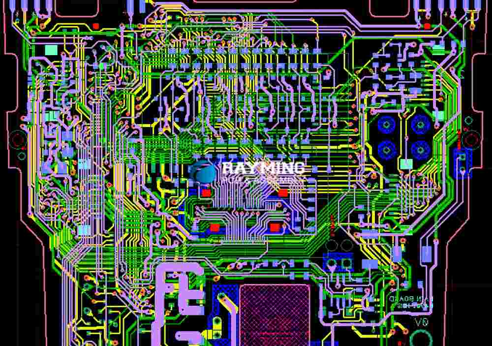
PCB stands for Printed Circuit Board, and a PCB file is a digital representation of the physical layout and design of a printed circuit board. These files contain all the necessary information required to manufacture the PCB, including the placement of electronic components, traces (copper connections), vias (conductive holes), solder pads, and other elements.
PCB files are typically created using specialized computer-aided design (CAD) software, known as PCB design tools or electronic design automation (EDA) software. These software applications allow engineers and designers to create schematics, lay out components, route traces, and generate manufacturing files.
Types of PCB Files
There are several common file formats used for PCB design and manufacturing. The most widely used formats include:
1. Gerber Files
Gerber files, also known as RS-274X files, are the industry-standard format for describing the printed circuit board image data. These files contain information about the copper layers, solder mask, silkscreen, and other layers of the PCB. Gerber files are vector-based and can be viewed and edited using various software tools.
Gerber files typically come in a set, with each file representing a different layer or aspect of the PCB design. Common Gerber file extensions include:
.gbror.pho: Copper layers (top, bottom, internal).gtsor.sms: Solder mask layers.gtoor.spo: Silkscreen layers.gblor.nco: NC drill file (describing drill holes).gboor.out: Board outline.gko: Keep-out layers
2. ODB++ Files
ODB++ (Open Data Base Plus Plus) is a comprehensive PCB data format developed by Mentor Graphics (now Siemens EDA). It combines all the necessary data for PCB manufacturing into a single file, including Gerber data, drill files, and other supplementary information.
ODB++ files have a .zip or .tgz file extension and contain a structured directory with various sub-files and folders representing different aspects of the PCB design.
3. IPC-2581 Files
IPC-2581 is an intelligent PCB data transfer format developed by the IPC (Association Connecting Electronics Industries). It is an XML-based format that combines all the necessary data for PCB manufacturing, similar to ODB++. IPC-2581 files have a .xml extension and can be efficiently compressed for transfer and storage.
4. EAGLE Files
EAGLE (Easily Applicable Graphical Layout Editor) is a popular PCB design software developed by Autodesk. EAGLE uses its own proprietary file format, typically with a .brd extension for board files and a .sch extension for schematic files.
5. Altium Designer Files
Altium Designer is another widely used PCB design software. It uses its own proprietary file formats, including .PcbDoc for PCB design files and .SchDoc for schematic files.
PCB File Contents
A complete set of PCB files typically contains the following information:
- Board Outline: The physical dimensions and shape of the PCB.
- Copper Layers: The layout of copper traces and planes on each layer of the PCB.
- Solder Mask: The areas where the solder mask (a protective coating) is applied or removed.
- Silkscreen: The text, logos, and other markings printed on the PCB for identification and reference.
- Drill Information: The locations, sizes, and types of drill holes (e.g., for vias, component holes, etc.).
- Component Footprints: The land patterns and pad locations for mounting electronic components.
- Electrical Connectivity: The connectivity information between traces, pads, and components.
- Board Stackup: The layer configuration and material information for the PCB layers.
- Assembly Information: Component reference designators, values, and other manufacturing data.
- Mechanical Information: Cutouts, edge bevels, and other mechanical features.
Importance of PCB Files
PCB files are crucial in the manufacturing process of printed circuit boards. They serve several important purposes:
- Manufacturing Data Transfer: PCB files provide a standardized way to transfer PCB design data from the design environment to the manufacturing facility, ensuring accurate and consistent production.
- PCB Fabrication: The Gerber and drill files are essential for the fabrication of the bare PCB, as they contain the necessary information for the photoplotter, drilling, and other production processes.
- Assembly and Inspection: Additional files, such as pick-and-place data, test points, and component information, aid in the automated assembly and inspection of populated PCBs.
- Documentation and Archiving: PCB files serve as a comprehensive documentation of the design, facilitating future modifications, repairs, or revisions.
PCB File Generation and Transfer
PCB design software typically includes tools for generating and exporting the necessary PCB files for manufacturing. The process typically involves the following steps:
- Design Entry: The PCB design is created using the schematic capture and layout tools within the design software.
- Design Rule Checking (DRC): The design is verified against a set of predefined rules to ensure compliance with manufacturing specifications and design constraints.
- CAM (Computer-Aided Manufacturing) Processing: The design data is processed to generate the various PCB file formats required for manufacturing, such as Gerber, ODB++, or IPC-2581.
- File Transfer: The generated PCB files are transferred to the manufacturing facility, often via secure file transfer protocols or cloud-based services.
- File Verification: The manufacturing facility verifies the integrity and completeness of the received PCB files before proceeding with production.
It is crucial to follow industry standards and best practices when generating and transferring PCB files to ensure compatibility, accuracy, and efficient communication between the design and manufacturing teams.
FAQs
- What is the difference between Gerber files and ODB++ files? Gerber files are a set of individual files representing different layers and aspects of the PCB design, while ODB++ is a comprehensive file format that combines all the necessary data for PCB manufacturing into a single file or package.
- Can I use PCB files from one design software in another software? PCB file formats like Gerber, ODB++, and IPC-2581 are industry-standard formats, allowing compatibility across different PCB design software and manufacturing environments. However, proprietary file formats (e.g., EAGLE, Altium Designer) may not be directly compatible with other software.
- What is the purpose of the drill file in a PCB file set? The drill file, typically called the NC drill file or Excellon file, contains information about the locations, sizes, and types of drill holes required for the PCB, such as component holes, vias, and mechanical cutouts.
- How are PCB files transferred to the manufacturing facility? PCB files are typically transferred to the manufacturing facility using secure file transfer protocols (e.g., SFTP, HTTPS) or cloud-based services. Some facilities may also accept physical media, such as USB drives or CDs, but digital transfer is more common and secure.
- What is the importance of Design Rule Checking (DRC) before generating PCB files? Design Rule Checking (DRC) is a crucial step in the PCB design process that verifies the design against a set of manufacturing rules and constraints. It helps identify and resolve potential issues, such as clearance violations, track width/spacing violations, and other design rule violations, before generating the final PCB files for manufacturing.


Leave a Reply