What is a Rheostat and How Does it Work?
A rheostat is a variable resistor that allows you to adjust the amount of current flowing through an electrical circuit. It works by changing the resistance in the circuit, which in turn changes the current flow according to Ohm’s law (V = IR, where V is voltage, I is current, and R is resistance).
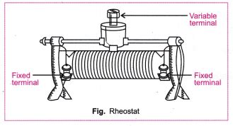
The key components of a rheostat are:
- Resistive element – usually a coil of wire or a strip of resistive material
- Sliding contact – allows you to vary the length of the resistive element that current flows through
- Terminals – connect the rheostat to the rest of the circuit
Here’s how a rheostat functions to vary resistance and current:
- The sliding contact is connected to one end of the resistive element
- As you move the sliding contact, it changes the effective length of resistive material that current must flow through
- A longer path through the resistive element = more resistance
- More resistance = less current flow through the circuit
- A shorter path through the resistive element = less resistance
- Less resistance = more current flow through the circuit
So in summary, sliding the contact changes the resistance, which varies the current. Rheostats allow you to smoothly adjust current from maximum to minimum.
Rheostat Schematic Symbol
The electrical schematic symbol for a rheostat is:
  /\/\/\/\
--|       |--
  |=>     |
  |_______|
The zig-zag line represents the resistive element. The arrow pointing to it represents the sliding contact. And the two lines on either end are the terminals.
Applications and Uses of Rheostats
Rheostats have many practical applications for controlling current flow. Some common uses include:
- Dimming lights
- Adjusting the speed of motors
- Controlling the temperature of heating elements
- Limiting current to sensitive circuits or components
- Setting the output voltage of generators
- Creating adjustable voltage dividers
- Functioning as adjustable loads for testing power supplies
Historically, rheostats were used extensively for controlling the brightness of lights. For example, a rheostat connected in series with an incandescent bulb allows dimming it from full brightness down to completely off by increasing the resistance.
Rheostats rated for higher power can control the speed of electric motors by varying the current delivered. More current = faster speed, while less current = slower speed.
In electronic circuits, small rheostats can provide an adjustable voltage reference or limit current to protect sensitive components. When configured as a voltage divider, a rheostat can create a variable output voltage.

Rheostat vs Potentiometer: What’s the Difference?
While rheostats and potentiometers may seem similar at first glance, they have important differences in construction and usage. Here’s a comparison of the key characteristics:
| Feature | Rheostat | Potentiometer |
|---|---|---|
| Terminals | 2 | 3 |
| Adjustability | Variable resistance | Variable voltage division |
| Typical Usage | Current limiting | Voltage control |
| Power Rating | Often high power (10W+) | Typically low power (<2W) |
| Resistive Element | Partial – only 2 terminal connected | Entire element always used |
| Resistive Element Taper | Usually linear | Linear or logarithmic |
| Typical Resistance | 1Ω to 100kΩ | 1kΩ to 1MΩ |
Construction Differences
The main physical difference is that rheostats have 2 terminals, while potentiometers have 3. In a rheostat, the sliding contact and one end of the resistive element are connected to the two terminals. Current enters one terminal, flows through part of the resistive element, and exits the other terminal.
In contrast, a potentiometer has the sliding contact as a third terminal. Current flows through the entire resistive element, entering one end terminal and exiting the other. The sliding contact terminal provides a voltage that varies depending on the contact position.
Schematic Symbol Differences
Here are the schematic symbols highlighting the construction differences:
Rheostat (2 terminals):
  /\/\/\/\
--|       |--
  |=>     |
  |_______|
Potentiometer (3 terminals):
  /\/\/\/\
--|       |--
  |=>     |
  |_______|
      |
      |
The potentiometer has that extra terminal connected to the sliding contact compared to the rheostat.
Functionality Differences
The key functional difference is that rheostats vary resistance while potentiometers provide an adjustable voltage divider.
In a rheostat circuit, the sliding contact is connected in series with the load. Changing the slider position directly varies the resistance in series with the load, thus varying the current through the load. The rheostat acts as an adjustable current limiter.
In contrast, a potentiometer is connected as a parallel voltage divider across a voltage source, with the load connected to the sliding contact. As the slider moves, it changes what fraction of the source voltage is dropped across the lower resistance portion and delivered to the load. The load “sees” an adjustable output voltage from 0V up to the full source voltage.
Another difference is rheostats often dissipate significant power and have high power ratings, commonly 10W to 100W or more. Potentiometers usually only dissipate a watt or two at most. Rheostats are used for higher current applications while potentiometers are suited for voltage signaling and lower power.
Usage Differences
Rheostats are commonly used for:
– Limiting current
– Adjusting the speed of motors
– Dimming lights
– Handling higher power levels
Some example rheostat applications:
– Adjusting a soldering iron temperature
– Dimming a stage spotlight
– Controlling a small motor speed
– Setting the output current of a power supply
Potentiometers are typically used for:
– Providing an adjustable reference voltage
– Controlling gains and levels in electronic circuits
– Audio volume controls
– User input devices like joysticks
– Lower power applications
Some common potentiometer applications:
– Volume knob on an audio amplifier
– Contrast adjustment on a display
– Feedback level in an op-amp circuit
– Voltage reference for a comparator
– Throttle or steering input in an RC car
While there are some overlapping uses, in general rheostats excel at handling power and current while potentiometers are better for voltage level adjustment. Understanding the differences allows you to pick the right component for your application.

Rheostat FAQ
What happens if I connect a load to the sliding terminal of a rheostat?
In normal use, a rheostat has the load connected between the two end terminals, not the slider. If you connect a load to the slider and one end, you are essentially using the rheostat as a potentiometer.
The load will receive a voltage that varies from 0V up to the full voltage drop across the rheostat, depending on the slider position. The current through the load will be limited by the resistance between the slider and the end terminal.
While this may work for very light loads, it’s generally not the intended use of a rheostat. Rheostats are designed to handle the full current of the circuit, not divide voltages. It’s better to use an actual potentiometer if you need an adjustable voltage divider.
Can a rheostat be used as a potentiometer?
Technically yes, but with caveats. You can use a rheostat as a potentiometer by connecting the load between the sliding contact and one end terminal, as discussed above. The rheostat will function as an adjustable voltage divider.
However, rheostats are not designed for this use and may have some drawbacks compared to a true potentiometer:
- The sliding contact on a rheostat may not be as durable or precise since it’s not intended for voltage sampling.
- Rheostats may have only linear tapers while potentiometers commonly offer linear or logarithmic tapers.
- A rheostat is usually bulkier and more expensive than a potentiometer for small signal applications.
So while you can use a rheostat as a potentiometer in a pinch, it’s generally better to use the proper component for the job. Potentiometers will give better performance and durability for voltage dividing uses.
What type of resistive element is used in a rheostat?
Rheostats can use several different materials for the resistive element, depending on the power handling needs and resistance value. Some common resistive elements in rheostats are:
-
Wirewound – A coil of resistive wire, often wound around a ceramic core. Provides high power handling and stability. Used in high power rheostats up to 100W or more.
-
Carbon composition – A mix of carbon powder and a binding agent. Provides lower cost and good power handling. Common in lower power rheostats up to about 10W.
-
Cermet – A ceramic and metal composite film. Offers better temperature stability and precision than carbon. Found in mid-range rheostats.
-
Conductive plastic – A resistive plastic film. Gives smooth and quiet adjustment. Used in precision rheostats for sensitive circuits.
The type of resistive element affects key parameters like the power rating, resistance tolerance, temperature coefficient, and lifespan. High power rheostats usually use wirewound elements, while smaller rheostats may use cermet or conductive plastic.
The taper, or how the resistance changes with slider position, is also important. Most rheostats have a linear taper where the resistance changes proportionally with position. Some specialty rheostats may have a logarithmic or reverse taper for particular applications.
What is the power rating of a rheostat?
The power rating indicates how much power the rheostat can safely dissipate without damage. It’s a key parameter to consider when selecting a rheostat for your application. Using a rheostat above its rated power can cause overheating, damage, and failure.
Rheostats are commonly available with power ratings from a few watts up to 100W or more. The exact power rating depends on the size, materials, and construction of the particular rheostat. In general, higher power rheostats will be larger and more expensive.
To determine the needed power rating, calculate the maximum power the rheostat will dissipate in your circuit. The power dissipated by the rheostat is given by:
P = I^2 * R
Where:
– P is power in watts
– I is the current through the rheostat in amps
– R is the resistance of the rheostat in ohms
For example, if a 50Ω rheostat has a maximum current of 1A flowing through it, the power dissipated is:
P = 1A^2 * 50Ω = 50W
So this application would require a rheostat rated for at least 50W. It’s good practice to choose a rheostat with some safety margin, so a 100W unit might be ideal here.
Always check the rheostat datasheet and ensure the actual power dissipation in your circuit will be within the rated limit. Proper sizing will ensure reliable and safe operation.
Can a rheostat be used as a variable resistor?
Yes, a rheostat is a type of variable resistor. A variable resistor is a general term for any resistor where the resistance value can be changed. There are several types of variable resistors, each with different construction and usage.
The three main types of variable resistors are:
-
Rheostat – Two terminals, variable resistance. Used to control current.
-
Potentiometer – Three terminals, variable voltage divider. Used to control voltage.
-
Trimpot (Trimmer Potentiometer) – Three terminals, small size, set-and-forget adjustment.
All of these types let you change the resistance, but in different ways and for different purposes. Rheostats and potentiometers are usually panel-mount types with a knob or slider for user adjustment. Trimpots are typically pcb-mount and adjusted with a screwdriver to set a calibration value.
Since a rheostat is a two-terminal variable resistor, it can certainly be used in applications needing an adjustable resistance. For example:
- Current limiting
- Adjusting motor speed
- Dimming lights
- Setting a delay time in an RC circuit
However, for applications needing a voltage divider, a potentiometer would be the better choice. The terms ‘potentiometer’ and ‘variable resistor’ are sometimes used interchangeably, but a rheostat has uniquely two terminals.
The key point is to pick the right type of variable resistor for your needs. Rheostats are great for current adjustment, but use a potentiometer when you need a voltage adjustment. Trimpots are best for infrequent calibration adjustment. Understanding the differences lets you select the optimal component for your design.


Leave a Reply