Introduction
Flex circuits, also known as flexible printed circuits or flex PCBs, are thin, bendable circuit boards that connect electronic components. They are made from flexible insulating substrate materials like polyimide or polyester with conductive traces printed or bonded on the surface. Flex circuits can be designed with intricate shapes to fit into tight spaces and movable configurations in modern electronic devices. They provide many advantages over traditional rigid circuit boards which make them ideal for use in a wide variety of applications.
Applications of Flex Circuits
Consumer Electronics
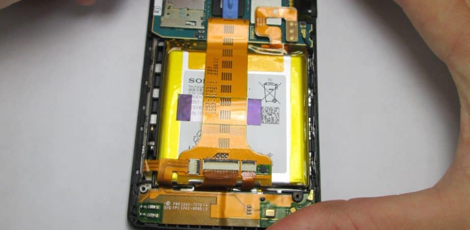
Flex circuits are widely used in consumer electronics like smartphones, tablets, wearables, and laptops which require thin and lightweight PCB solutions. The flex boards interconnect the miniature components inside these devices and provide movable interconnections for displays, cameras, button pads and other parts. Using flex circuits instead of rigid boards allows creating slim and compact product designs. Some common examples include:
- Displays – connecting LCD/OLED displays to the mainboard in cell phones and tablets. The flex allows the display to fold or move while maintaining electrical connections.
- Hinges – linking two boards or a board and display over a hinge, like in laptops and foldable devices. The flex bends repeatedly without failure.
- Buttons – connecting the button pads to the device logic board in phones, remote controls etc. The flex allows pressing buttons without cracking solder joints.
- Cameras – flexible connectors for camera modules that can be oriented in different positions.
- Batteries – thin interconnects between batteries and circuit boards that accommodate battery swelling.
Medical Devices
Flex circuits are an important enabling technology in medical devices like hearing aids, blood glucose monitors, surgical tools and implants. Being thin and lightweight, they can integrate seamlessly into wearable and implantable devices. Some uses include:
- Interconnections for imaging sensors like endoscopes, pillcams and catheter cameras. The flex boards provide multi-layer signal routing in the tight tubular medical instrument designs.
- Wearable health monitors and insulin pumps which conform to the user’s body.
- Sensors and connections for smart surgical tools that fit into tiny spaces.
- Implants like pacemakers and neurostimulators where the flexible circuits can wrap around internal organs.
Automotive Applications
The automotive industry utilizes flex circuits for connecting many electronic modules throughout the vehicle. Flexible circuits withstand vibrations and thermal cycling in the engine bay and exterior parts of a car. Example automotive uses:
- Sensors in engine compartments, under the hood, in suspensions etc. where rigid boards cannot survive.
- Heated seats with flex circuits in the cushions interconnected via folding patterns.
- Touchpads and control panels in the interior with flex circuits behind the displays.
- Flex antenna connections that can mount on curved surfaces.
- Circuits to control exterior lights with dynamic bending capacity.
Defense and Aerospace
Demanding defense and aerospace systems leverage the advantages of flex circuits as well. Rugged flex boards work reliably in the extreme conditions seen in these applications. Some examples:
- Missiles and ammunition with flex providing interconnections that withstand high g-forces and vibrations.
- Avionics systems where size and weight minimization is critical.
- Spacecraft assemblies able to function in large temperature swings and radiation environments.
- Wearable tech and electronic textiles for soldiers utilizing embedded flex circuits.
- Radar and electronic warfare systems using flex boards conformal to the product shape.
Other Industries
Many other products and sectors also employ flexible printed circuits to meet size, weight and reliability requirements:
- Industrial electronics in manufacturing systems, robotics, instrumentation etc.
- White goods like washing machines and refrigerators.
- LED lighting fixtures.
- Solar panels
- POS and ATM machines.
So in summary, flex circuits are an enabling technology with applications across consumer electronics, medical, automotive, aerospace, industrial and other fields. Their key advantages are light weight, small size, shape conformability, ruggedness and dynamic flexing capacity compared to standard rigid circuit boards. The rapid growth in flexible electronics will drive expanded use of innovative flex circuit designs and manufacturing processes in the future.
Benefits and Advantages of Flex Circuits
Why are flex circuits used so widely? What characteristics make them the PCB of choice in many applications? Here are some of the main benefits provided by flex circuits:
Flexible – Can be bent, folded and twisted repeatedly to route traces into 3D spaces and movable configurations not possible with rigid boards. Vibration resistant.
Thin and lightweight – Flexible substrate materials like polyimide are thinner than standard FR4. This allows compact and slim product designs by embedding circuits into tight spaces.
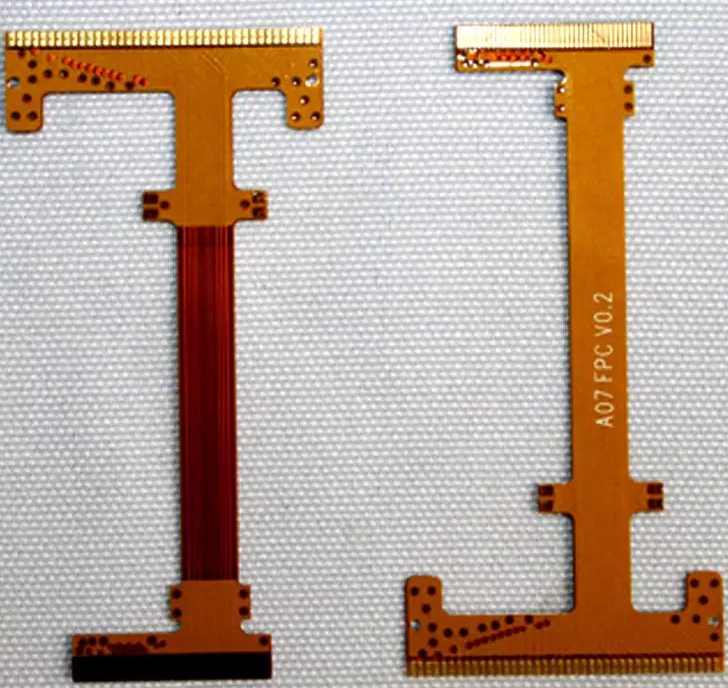
Highly customizable – Flex circuits can be manufactured in a vast variety of shapes, sizes and layouts to fit the design needs. Parts can be embedded during fabrication.
Durable – Withstands harsh environments like temperature extremes, moisture, chemicals and mechanical shocks. Ideal for rugged applications.
High Density – Small traces and spaces down to 15 microns enable dense interconnect routing. Permit miniaturization.
Low Cost – Eliminates connectors and simplifies assembly vs. rigid boards, reducing overall system cost.
High Speed – Careful impedance control allows flex circuits to work at multi-Gbps signaling speeds.
Low Power – Thin materials reduce capacitance for lower power consumption compared to traditional PCBs.
In summary, the combination of flexibility, small size, light weight, durability, customizability, density, cost, speed and low power makes flex the ideal interconnect solution for modern electronic product design in many industries.
Typical Components of a Flex Circuit
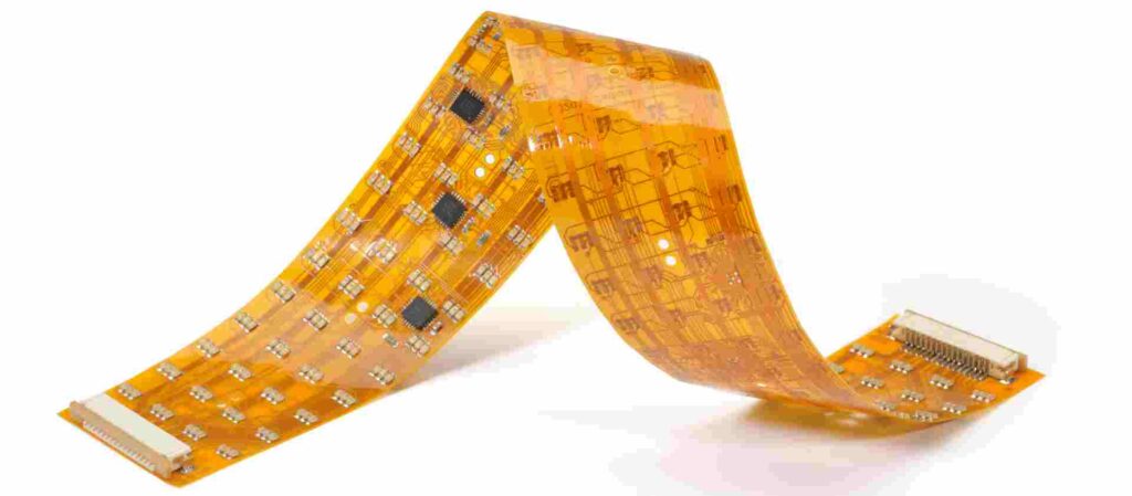
While there are many variations, most flex circuits consist of some common fundamental components:
Flexible Substrate – The base of the flex circuit is a thin insulating flexible substrate like polyimide or polyester. This gives the PCB its bendable traits.
Conductors – Typically copper traces transfer signals and power between components. There may be single or multiple conductive layers.
Bonding Adhesive – Adhesive films like acrylic or epoxy glue the copper layers to the substrate.
Coverlay – A solder mask layer covers the conductors for electrical isolation and mechanical protection.
Stiffeners – Areas with no flexing may have a rigid stiffener bonded to the substrate for structural support.
Terminations – Pads, lands or connectors attach at the ends of conductors to connect components or cables.
Legends – Screen printed labels, lines, shapes etc. provide circuit identification and markings.
Reinforcement – Additional layers of insulating material may reinforce high flex zones prone to wear and tear.
Components – Passive parts, ICs and other components can be directly mounted onto the flex board.
So in summary, a flex circuit integrates flexible insulating material, patterned copper traces, protective coatings, termination points and optionally integrated components into a thin, robust and customizable interconnect solution.
Flex Circuit Design Considerations
Designing a successful flex circuit requires considering several important factors:
Circuit Layout – Position components and route traces optimally taking into account the flexing, folding, twisting and dynamic movements needed.
Conductor Width/Spacing – Match trace dimensions to current levels and impedance targets. Account for flexibility effects.
Substrate Thickness – Thinner for maximum flexibility and bend radius, thicker for rigidity and durability.
Stiffener Location – Strategically reinforce sections that do not flex with bonded stiffeners.
High Flex Areas – Use special materials like polyimide at fold joints and dynamic sections.
Adhesives – Select bonding adhesives compatible with flexing movements and environmental conditions.
Termination Types – Choose the right pad, land and connector types based on connectivity needs.
Fabrication Factors – Consider capabilities of manufacturing processes like photolithography and metal etching.
Testing – Validate electrical connectivity, continuity and mechanical durability with flexing.
Careful consideration of these parameters allows creating a robust flex circuit optimized for the product application requirements.
Flex Circuit Manufacturing Process
Producing flex circuits requires specialized fabrication techniques adapted to handle flexible substrates. Here are the typical manufacturing steps:
Substrate Preparation – The flexible base material like polyimide or polyester is cut to the required shape and size. Holes may be punched.
Conductor Formation – Photolithography followed by etching patterns the copper foil into circuit traces and features.
Coverlay Application – Liquid solder mask coats over the traces and acts as a protective electrical insulator.
Layer Alignment – Conductor layers are carefully aligned and bonded with adhesive films.
Component Attachment – Parts are soldered or adhered onto the flex board surface.
Termination Creation – Pads, lands, connectors are added to ends of circuit traces.
Legend Printing – Prints or photolithography defines board markings and labels.
Testing – Continuity, connectivity and function are validated before shipping.
The specialized materials, fabrication techniques and quality controls result in reliable, high-performance flex circuits.
Future Outlook for Flexible Circuits
The applications for flex circuits and flexible electronics continue to expand rapidly with the progress in materials, processes and integrated circuit technologies. Here are some trends influencing future growth:
- Miniaturization – Flex enables further size and weight reduction in small, portable and wearable devices.
- Foldables – Flexible displays and circuits allow new form factors like foldable and rollable screens.
- Stretchables – Novel stretchable interconnects integrate electronics with clothing, fabrics, biomedical devices etc.
- Printed Electronics – Printing processes can directly fabricate flex circuit traces for low cost and customization.
- 3D Structures – Flex shapes not producible with rigid boards open new design possibilities.
- Functional Integration – Embedding passive components, sensors and ICs provide “flexible systems”.
The unique properties of flex circuits coupled with technology improvements will enable a new generation of flexible, conformable and stretchable electronic products over the coming decade in many industries.
Frequently Asked Questions
Here are some common FAQs about flex circuits:
Q: How are flex circuits different from rigid printed circuit boards?
A: Flex circuits use thin flexible substrate materials like polyimide instead of rigid FR4 allowing dynamic bending and twisting. They can take on 3D shapes not possible with standard PCBs.
Q: Can components be mounted directly on flex circuits?
A: Yes, components can be soldered or adhered onto the flex board surface. Care must be taken in positioning to minimize stresses from flexing.
Q: What are some key metrics for specifying flex circuits?
A: Critical parameters are number of layers, overall dimensions, trace widths/spacings, flexible and rigid areas, substrate material and thickness, minimum bend radius etc.
Q: Is special PCB design software needed for flex circuits?
A: While standard PCB software can be used, dedicated flex/rigid-flex design tools provide additional features for optimal layout.
Q: How are most flex circuits fabricated and manufactured?
A: Photolithography patterning followed by wet etching of copper foils is the most common fabrication method. Laser direct imaging is also sometimes used.
Q: What type of testing is performed on completed flex circuits?
A: In addition to electrical testing, flex circuits must undergo thorough mechanical validation with repeated bending, twisting and folding to ensure durability.
Q: What are some limitations or disadvantages of flexible circuits?
A: Limitations include lower circuit density compared to rigid boards, higher fabrication costs in low volumes, and reduced stiffness for some applications.
In summary, flex circuits provide a unique interconnect solution combining flexibility, small size, light weight and ruggedness for mission-critical electronics in the most demanding applications.


Leave a Reply