Introduction
Printed Circuit Boards (PCBs) are the backbone of modern electronics. They are used in almost every electronic device, from smartphones and laptops to industrial equipment and aerospace systems. The process of designing, manufacturing, and testing PCBs is complex and involves multiple stakeholders, including designers, engineers, manufacturers, and customers. Effective communication and collaboration among these stakeholders are critical for the success of any PCB project.
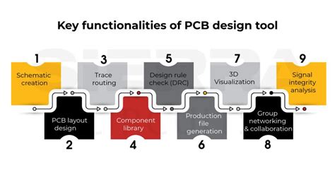
One of the most important tools for facilitating communication and collaboration in the PCB business process is visualization. PCB Visualization allows stakeholders to see the design, layout, and functionality of a PCB in a clear and intuitive way. It helps to identify potential issues early in the design process, reduce errors and rework, and improve the overall quality of the final product.
In this article, we will explore the importance of PCB visualization throughout the whole business process, from design to manufacturing and testing. We will discuss the different types of PCB visualizations, their benefits, and best practices for creating effective visualizations. We will also answer some frequently asked questions about PCB visualization.
The Importance of PCB Visualization
Facilitating Communication and Collaboration
One of the main benefits of PCB visualization is that it facilitates communication and collaboration among stakeholders. PCBs are complex systems that require input from multiple disciplines, including electrical engineering, mechanical engineering, and manufacturing. Each discipline has its own language, tools, and processes, which can make communication and collaboration challenging.
PCB visualization provides a common language that everyone can understand. It allows stakeholders to see the PCB design in a visual format, rather than just as a set of abstract schematics or data. This makes it easier for stakeholders to identify potential issues, suggest improvements, and collaborate on solutions.
For example, a mechanical engineer can use PCB visualization to check the physical layout of the board and ensure that it fits within the enclosure. An electrical engineer can use visualization to verify the signal integrity and power distribution of the board. A manufacturer can use visualization to identify potential manufacturing issues and suggest design changes to improve manufacturability.
Reducing Errors and Rework
Another benefit of PCB visualization is that it helps to reduce errors and rework. PCBs are complex systems with many interconnected components and signals. Even a small error in the design or layout can have significant consequences downstream, leading to delays, additional costs, and reduced quality.
PCB visualization allows designers and engineers to catch errors early in the design process, before they become more difficult and expensive to fix. By visualizing the PCB design in 3D, designers can identify potential issues such as component collisions, signal integrity problems, and thermal management issues. They can then make adjustments to the design to address these issues before sending the design to manufacturing.
For example, a designer might use PCB visualization to check the clearance between components and ensure that there are no collisions. They might also use visualization to analyze the signal integrity of high-speed signals and make adjustments to the layout to minimize crosstalk and reflections.
Improving Quality and Reliability
PCB visualization also helps to improve the overall quality and reliability of the final product. By catching errors early and making design improvements based on visualization, designers and engineers can create a higher-quality PCB that is more reliable and performs better in the field.
For example, a designer might use PCB visualization to optimize the placement of components for better thermal management. They might also use visualization to analyze the mechanical stress on the board and make changes to improve its durability and reliability.

Types of PCB Visualizations
There are several types of PCB visualizations that are commonly used in the industry. Each type of visualization serves a different purpose and provides different benefits. Some of the most common types of PCB visualizations include:
2D Visualizations
2D visualizations are the most basic type of PCB visualization. They provide a flat, top-down view of the PCB design, showing the placement of components, traces, and other features. 2D visualizations are often used for initial design reviews and for communicating the basic layout of the board to stakeholders.
| Advantages | Disadvantages |
|---|---|
| Easy to create and understand | Limited information about the 3D structure of the board |
| Can be used for initial design reviews | Does not show potential issues related to component height or clearance |
| Provides a clear overview of the board layout | May not accurately represent the final manufactured board |
3D Visualizations
3D visualizations provide a more detailed and accurate representation of the PCB design. They show the board in three dimensions, including the height and placement of components, the thickness of the board, and the routing of traces through different layers.
3D visualizations are often used for more advanced design reviews and for analyzing potential issues related to component placement, signal integrity, and thermal management. They can also be used to create photorealistic renderings of the final product for marketing and sales purposes.
| Advantages | Disadvantages |
|---|---|
| Provides a more accurate and detailed representation of the board | Can be more time-consuming and resource-intensive to create |
| Allows for analysis of potential issues related to component placement and signal integrity | May require specialized software and expertise to create and interpret |
| Can be used to create photorealistic renderings for marketing and sales purposes | May not be necessary for simpler designs or early-stage projects |
Interactive Visualizations
Interactive visualizations take 3D visualizations a step further by allowing users to interact with the model in real-time. Users can rotate, zoom, and pan the model to get a better understanding of the board structure and layout. They can also select individual components or traces to get more detailed information about their properties and connections.
Interactive visualizations are often used for collaborative design reviews and for training purposes. They allow stakeholders to explore the PCB design in a more intuitive and engaging way, and to ask questions and provide feedback in real-time.
| Advantages | Disadvantages |
|---|---|
| Allows for real-time interaction and exploration of the board model | Requires specialized software and hardware to create and view |
| Provides a more engaging and intuitive way to understand the board structure and layout | Can be more resource-intensive and time-consuming to create |
| Can be used for collaborative design reviews and training purposes | May not be necessary for simpler designs or smaller teams |
Augmented Reality (AR) Visualizations
Augmented Reality (AR) visualizations are a newer type of PCB visualization that allows users to view the PCB design in the context of the real world. Users can use a smartphone or tablet to overlay a 3D model of the PCB onto a physical object, such as a prototype or a finished product.
AR visualizations are often used for training and maintenance purposes. They allow technicians and engineers to see how the PCB fits into the larger system, and to identify potential issues or areas for improvement. They can also be used for marketing and sales purposes, allowing customers to see how the PCB will look and function in the final product.
| Advantages | Disadvantages |
|---|---|
| Allows users to view the PCB design in the context of the real world | Requires specialized software and hardware to create and view |
| Provides a more immersive and engaging way to understand the PCB design | Can be more resource-intensive and time-consuming to create |
| Can be used for training, maintenance, and marketing purposes | May not be necessary for simpler designs or smaller teams |

Best Practices for Creating Effective PCB Visualizations
Creating effective PCB visualizations requires a combination of technical skills, design knowledge, and communication abilities. Here are some best practices for creating PCB visualizations that are clear, accurate, and informative:
Start with a Clear Purpose
Before creating a PCB visualization, it’s important to have a clear understanding of its purpose and intended audience. Different types of visualizations may be more appropriate for different purposes and audiences. For example, a 2D visualization may be sufficient for an initial design review with a small team, while an interactive 3D visualization may be more appropriate for a collaborative design review with multiple stakeholders.
Use Appropriate Software and Tools
Creating effective PCB visualizations requires the use of appropriate software and tools. There are many different PCB design and visualization tools available, each with its own strengths and weaknesses. Some of the most popular tools include Altium Designer, Cadence Allegro, and Autodesk EAGLE.
When choosing a tool, it’s important to consider factors such as ease of use, compatibility with existing systems and processes, and the specific features and capabilities needed for the project. It’s also important to ensure that all stakeholders have access to and are trained on the chosen tool.
Use Consistent and Clear Labeling
One of the most important aspects of creating effective PCB visualizations is clear and consistent labeling. All components, traces, and other features should be labeled accurately and consistently throughout the visualization. This helps to ensure that all stakeholders are using the same terminology and can easily identify and discuss specific parts of the design.
When labeling components, it’s important to use industry-standard nomenclature and to include relevant information such as part numbers, values, and tolerances. Traces should be labeled with their signal names and any relevant electrical properties such as impedance and propagation delay.
Use Color and Contrast Effectively
Color and contrast can be powerful tools for highlighting important features and making PCB visualizations more readable and engaging. However, it’s important to use color and contrast effectively and consistently.
When using color, it’s important to choose a color scheme that is easy to read and interpret. High-contrast color schemes, such as black on white or white on black, are often the most effective for PCB visualizations. It’s also important to use color consistently throughout the visualization, using the same colors for the same types of features or signals.
When using contrast, it’s important to ensure that important features are easily distinguishable from the background and from each other. This can be achieved through the use of different line weights, shading, or other visual cues.
Provide Context and Annotation
PCB visualizations should not exist in a vacuum, but should be accompanied by appropriate context and annotation. This can include information about the overall system architecture, the purpose and functionality of specific components or subsystems, and any relevant design constraints or requirements.
Annotations can be used to provide additional information or explanations about specific parts of the visualization. For example, an annotation might be used to explain the function of a particular component or to highlight a potential issue or area for improvement.
Collaborate and Iterate
Creating effective PCB visualizations is an iterative process that requires collaboration and feedback from all stakeholders. It’s important to involve stakeholders early in the design process and to solicit their input and feedback throughout the visualization process.
Collaboration can be facilitated through the use of interactive visualizations and collaborative design review tools. These tools allow stakeholders to explore the visualization together in real-time, ask questions, and provide feedback and suggestions for improvement.
Iteration is also important for refining and improving the visualization over time. As the design evolves and new information becomes available, the visualization should be updated and refined to reflect these changes.

Frequently Asked Questions
What is the difference between 2D and 3D PCB visualization?
2D PCB visualization provides a flat, top-down view of the PCB design, showing the placement of components, traces, and other features. 3D PCB visualization, on the other hand, provides a more detailed and accurate representation of the PCB design, showing the board in three dimensions, including the height and placement of components, the thickness of the board, and the routing of traces through different layers.
What are the benefits of interactive PCB visualization?
Interactive PCB visualization allows users to interact with the model in real-time, rotating, zooming, and panning the model to get a better understanding of the board structure and layout. It also allows users to select individual components or traces to get more detailed information about their properties and connections. This makes it a powerful tool for collaborative design reviews and training purposes.
What software tools are used for creating PCB visualizations?
There are many different PCB design and visualization tools available, each with its own strengths and weaknesses. Some of the most popular tools include Altium Designer, Cadence Allegro, and Autodesk EAGLE. The choice of tool depends on factors such as ease of use, compatibility with existing systems and processes, and the specific features and capabilities needed for the project.
How can color and contrast be used effectively in PCB visualization?
Color and contrast can be powerful tools for highlighting important features and making PCB visualizations more readable and engaging. High-contrast color schemes, such as black on white or white on black, are often the most effective for PCB visualizations. Color should be used consistently throughout the visualization, using the same colors for the same types of features or signals. Contrast should be used to ensure that important features are easily distinguishable from the background and from each other.
What is the role of collaboration and iteration in creating effective PCB visualizations?
Creating effective PCB visualizations is an iterative process that requires collaboration and feedback from all stakeholders. Collaboration can be facilitated through the use of interactive visualizations and collaborative design review tools, which allow stakeholders to explore the visualization together in real-time, ask questions, and provide feedback and suggestions for improvement. Iteration is important for refining and improving the visualization over time, as the design evolves and new information becomes available.
Conclusion
PCB visualization is a critical tool for facilitating communication, collaboration, and quality throughout the PCB business process. By providing a clear and accurate representation of the PCB design, visualization helps to identify potential issues early, reduce errors and rework, and improve the overall quality and reliability of the final product.
There are many different types of PCB visualizations, each with its own strengths and weaknesses. 2D visualizations provide a basic overview of the board layout, while 3D visualizations offer a more detailed and accurate representation of the board structure. Interactive visualizations allow for real-time exploration and collaboration, while AR visualizations provide an immersive and contextual view of the PCB design.
To create effective PCB visualizations, it’s important to start with a clear purpose, use appropriate software and tools, and follow best practices for labeling, color and contrast, context and annotation, and collaboration and iteration. By following these best practices and continually refining and improving the visualization over time, PCB designers and engineers can create visualizations that are clear, accurate, and informative, and that help to drive success throughout the PCB business process.


Leave a Reply