What is the TSOP-1738 IR Receiver Module?
The TSOP-1738 is a 3-pin IR receiver module that operates at a carrier frequency of 38 kHz. It contains a photodiode, amplifier, automatic gain control, bandpass filter, demodulator, and output stage all in a compact epoxy package:
| Pin | Name | Description |
|---|---|---|
| 1 | OUT | Active low output |
| 2 | GND | Ground |
| 3 | VS | Supply voltage (2.5 V to 5.5 V) |
When the TSOP-1738 detects a 38 kHz IR signal, the output pin goes low. This digital output can be read by a microcontroller or other logic circuit to determine if an IR signal is present.
How IR Communication Works
To understand how the TSOP-1738 is used, it helps to know the basics of how IR communication works:
- An IR LED transmitter is pulsed on and off at a carrier frequency, typically 38 kHz for consumer electronics. The pulses are modulated to encode data.
- The IR light travels to the IR receiver (like the TSOP-1738). Ambient light and IR at other frequencies is ignored.
- The IR receiver demodulates the 38 kHz signal and outputs a logic low when an in-band IR signal is detected.
- A microcontroller or other circuit decodes the output from the IR receiver to extract the transmitted data.
Common IR communication protocols like NEC, Sony SIRC, Philips RC5/RC6 differ in their exact modulation schemes but all follow this general principle.

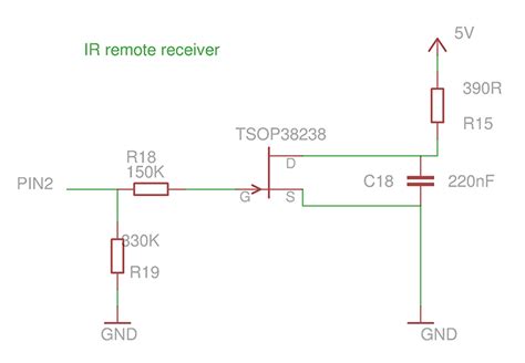
Basic TSOP-1738 Circuit
Here is the minimum circuit required to use the TSOP-1738 IR receiver:
        ------------
  VS --|3         1|-- OUT
       |           |
  GND --|2         |
        ------------
           | |
        (IR input)
Simply connect VS to a power supply between 2.5V to 5.5V, GND to ground, leave the output floating or connect a pull-up resistor to VS. When an IR signal is detected, the open-drain output will pull low.
For reliable operation, it’s best to add a power supply filter capacitor close to the TSOP-1738:
        ------------
  VS --|3         1|-- OUT
       |           |
      --- 4.7 uF   |
       |           |
  GND --|2         |
        ------------
           | |
        (IR input)
A 4.7 uF to 10 uF ceramic capacitor from VS to GND helps reject power supply noise that could interfere with the high-gain IR receiver.

Interfacing the TSOP-1738 to a Microcontroller
In most cases, you’ll want to connect the output of the TSOP-1738 to a microcontroller so it can decode the received IR signals. Here’s how to interface it with common microcontrollers:
With Arduino:
        ------------
  5V --|3         1|---------------| Arduino pin 2
       |           |
      --- 4.7 uF   |
       |           |
 GND --|2         |
        ------------
           | |
        (IR input)
Connect VS to 5V, GND to GND, and OUT to any Arduino digital input pin. Then in your code, attach an interrupt handler to the input pin to detect incoming IR signals.
With Raspberry Pi:
        ------------
 3.3V --|3         1|---------------| RPi GPIO 18
        |           |
       --- 4.7 uF   |
        |           |
  GND --|2         |
         ------------
            | |
         (IR input)
Connect VS to 3.3V, GND to GND, and OUT to any free GPIO pin. Be sure to use a 3.3V compatible input pin, not a 5V tolerant pin. Then in your code, set the GPIO as an input and use edge detection to receive IR signals.
With ESP8266/ESP32:
        ------------
  3.3V --|3         1|---------------| ESP pin 14
         |           |
        --- 4.7 uF   |
         |           |
   GND --|2         |
          ------------
             | |
          (IR input)
Connect VS to 3.3V, GND to GND, and OUT to any free GPIO. Configure the GPIO as an input and use the ESP’s edge or pulse counter to receive and decode IR.
For other microcontrollers, the interfacing is similar – connect power and ground, and read the output with a digital input capable of edge or pulse detection for the IR protocol of interest.

Selecting a Resistor for the TSOP-1738 Output
The TSOP-1738’s output is open-drain, meaning it pulls low but does not actively drive high. This allows it to interface with any logic level (3.3V, 5V, etc.) but means a pull-up is required to restore the output high.
Many microcontrollers have built-in weak pull-up resistors that eliminate the need for an external pull-up on the TSOP-1738 output. If one is needed, a 10K resistor from OUT to VS is recommended as a starting point.
The ideal pull-up value depends on the desired IR receive range and interference immunity. A lower value speeds up edges for better range but reduces noise immunity. Some experimentation may be required.
TSOP-1738 Sensitivity Adjustment
The TSOP-1738 has excellent sensitivity, typically able to receive IR signals from over 10 meters away. In some cases, this high sensitivity can cause problems – ambient IR, overly strong signals, or reflections may trigger false receive events.
If IR reception is unreliable, try these tips to adjust the TSOP-1738’s sensitivity:
- Place a small piece of shrink tubing or other opaque cover over the TSOP-1738’s lens to reduce sensitivity. Experiment with different sizes.
- Aim the IR transmitter and receiver away from nearby surfaces to prevent reflections.
- Add an IR bandpass filter, such as the Vishay TSOP34838 or Wratten 87C.
- Reduce the strength of the IR transmitter by reducing its current or adding a resistor in series.
With some trial and error, the right sensitivity can be achieved even for challenging environments.
Decoding IR Signals from the TSOP-1738
Once you have the TSOP-1738 properly connected and receiving IR signals, the final step is decoding the signals into useful data. The specifics depend on the IR protocol used by your transmitting device.
Popular protocols like NEC, Sony SIRC, and Philips RC5 encode data bits by varying the duration of the 38 kHz IR pulses. A microcontroller can measure the duration of each pulse or gap using a timer or input capture peripheral.
Here are some tips for reliable IR decoding:
-
Use hardware interrupts or capture/compare peripherals to accurately timestamp each edge of the IR signal. Software pulse duration measuring is less precise.
-
Implement a state machine to track the IR decoding process. Typical states include idle, receiving lead code, receiving address, receiving data, etc.
-
Use liberal guard times to allow for variations in IR timing. Allow +/- 20% tolerance initially.
-
Validate the overall structure of the IR packet – lead code, correct number of bits, matching inverse bits, etc. Reject invalid packets.
-
Implement a retry mechanism since not all IR transmissions will be received on the first attempt.
With proper hardware, connection, sensitivity adjustment, and robust decoding software, you’ll have a reliable IR receiver solution using the TSOP-1738.
Conclusion
The TSOP-1738 is an excellent 38 kHz IR receiver module for adding IR communication to your projects. By following the connection and interfacing guidelines in this article, you’ll be well on your way to building circuits that can receive and decode IR signals from remote controls, beacons, and more.
FAQ
What is the range of the TSOP-1738 IR receiver?
The TSOP-1738’s range depends on the strength of the IR transmitter, but it can typically receive signals from over 10 meters away under ideal conditions. Range is affected by ambient lighting, reflections, transmitter current, and any obstructions between the transmitter and receiver.
Can the TSOP-1738 be used for transmitting IR signals?
No, the TSOP-1738 is a receiver only. It cannot emit IR light. For transmitting, you need an IR LED and driver circuit. Pair an IR LED transmitter with a TSOP-1738 receiver for two-way IR communication.
Does the TSOP-1738 have a built-in decoder?
No, the TSOP-1738 only demodulates the 38 kHz IR signal and outputs a logic-level waveform. An external microcontroller or dedicated decoder IC is required to convert the output of the TSOP-1738 into the original data bits according to the IR protocol in use.
Is the TSOP-1738 compatible with all IR remote controls?
The TSOP-1738 is compatible with any remote using 38 kHz modulation, which is the most common. It can receive signals using NEC, Sony SIRC, Philips RC5/RC6, and most other consumer electronics IR protocols. It cannot receive from IR remotes that use different carrier frequencies like 36 kHz or 40 kHz.
What happens if the TSOP-1738 OUT pin is left floating?
Leaving the OUT pin floating puts it in a high-impedance state. The voltage on OUT will be indeterminate and may trigger spurious receive events. For reliable operation, OUT should be connected to a microcontroller input or pull-up resistor so that it switches cleanly between logic high and low.


Leave a Reply