What is a Trimpot?
A trimpot, short for trimming potentiometer, is a small variable resistor used for fine adjustments and calibration in electronic circuits. Unlike regular potentiometers that are typically adjusted by the end user, trimpots are designed to be set once during manufacturing or servicing and then left in that position.
Trimpots come in various sizes, resistance ranges, and configurations to suit different applications. They are commonly found in electronic devices such as sensors, power supplies, amplifiers, and control systems where precise voltage or current adjustments are required.
Trimpot Pinout and Configuration
Basic Trimpot Structure
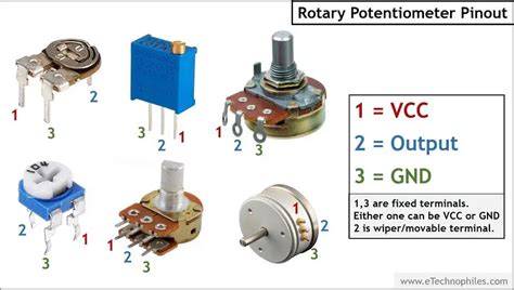
A typical trimpot consists of three terminals or pins:
- One end of the resistive element (Pin 1)
- Wiper or sliding contact (Pin 2)
- Other end of the resistive element (Pin 3)
The resistive element is a strip of resistive material, often made of carbon or cermet (ceramic-metal composite), with a sliding contact that moves along its length. As the wiper moves, it changes the resistance between the wiper and the two ends of the resistive element.
Trimpot Pinout Variations
Trimpots come in different packages and Pinout Configurations. The most common ones are:
Single-Turn Trimpot
Single-turn trimpots have a rotational range of about 270 degrees. They typically have three pins arranged in a triangular or inline configuration.
| Pin | Function |
|---|---|
| 1 | Resistive element end 1 |
| 2 | Wiper |
| 3 | Resistive element end 2 |
Multi-Turn Trimpot
Multi-turn trimpots offer more precise adjustments by providing multiple turns of the adjustment screw. They usually have three pins arranged in a square or inline configuration.
| Pin | Function |
|---|---|
| 1 | Resistive element end 1 |
| 2 | Wiper |
| 3 | Resistive element end 2 |
Surface Mount Trimpot (SMD)
Surface mount trimpots are designed for automated assembly on printed circuit boards (PCBs). They have a low profile and can have various pin arrangements depending on the package size and manufacturer.
Common SMD trimpot packages include:
- SOT-23
- SOT-89
- SOT-143
- SOT-223
- SOT-353
The pinout for SMD trimpots may vary, so it’s essential to refer to the manufacturer’s datasheet for the specific device.

Using Trimpots in Electronic Circuits
Voltage Divider
One of the most common uses of trimpots is in voltage divider circuits. A voltage divider allows you to obtain a variable voltage output by adjusting the trimpot’s resistance.
To create a voltage divider, connect the trimpot as follows:
- Connect one end of the resistive element (Pin 1 or 3) to the input voltage (Vin).
- Connect the other end of the resistive element (Pin 3 or 1) to ground (GND).
- Connect the wiper (Pin 2) to the output voltage (Vout).
The output voltage (Vout) is determined by the following equation:
Vout = Vin * (Rwiper / Rtotal)
Where:
– Rwiper is the resistance between the wiper and the grounded end of the resistive element.
– Rtotal is the total resistance of the trimpot.
By adjusting the trimpot’s wiper position, you can vary the output voltage between 0V and Vin.
Current Adjustment
Trimpots can also be used to adjust current in a circuit. By placing a trimpot in series with a load, you can control the current flowing through the load by varying the trimpot’s resistance.
To use a trimpot for current adjustment:
- Connect one end of the resistive element (Pin 1 or 3) to the voltage source.
- Connect the wiper (Pin 2) to the load.
- Connect the other end of the resistive element (Pin 3 or 1) to ground (GND).
The current flowing through the load is determined by Ohm’s law:
I = V / R
Where:
– I is the current in amperes (A)
– V is the voltage across the load in volts (V)
– R is the total resistance (trimpot + load) in ohms (Ω)
By adjusting the trimpot’s resistance, you can control the current flowing through the load.
Sensor Calibration
Trimpots are often used to calibrate sensors, such as temperature, pressure, or Light Sensors. By adjusting the trimpot, you can fine-tune the sensor’s output to match a known reference value.
For example, consider a temperature sensor that outputs a voltage proportional to the measured temperature. To calibrate the sensor:
- Expose the sensor to a known temperature (e.g., an ice bath at 0°C or boiling water at 100°C).
- Measure the sensor’s output voltage.
- Adjust the trimpot until the output voltage matches the expected value for the known temperature.
Repeat this process for multiple reference points to ensure accurate calibration across the sensor’s operating range.

Trimpot Selection Considerations
When selecting a trimpot for your application, consider the following factors:
-
Resistance range: Choose a trimpot with a resistance range suitable for your circuit requirements.
-
Power rating: Ensure the trimpot can handle the expected power dissipation in your circuit.
-
Adjustment type: Single-turn trimpots are easier to adjust but offer less precision than multi-turn trimpots.
-
Package: Select a package that fits your PCB layout and assembly process (e.g., through-hole or surface mount).
-
Environmental factors: Consider the operating temperature range, humidity, and other environmental factors that may affect the trimpot’s performance.
-
Precision and stability: For critical applications, choose trimpots with tight tolerance, low temperature coefficient, and good long-term stability.
Always refer to the manufacturer’s datasheet for detailed specifications and recommendations.

FAQ
- What is the difference between a trimpot and a regular potentiometer?
-
A trimpot is designed for fine adjustments and calibration, typically set once and left in position. Regular potentiometers are designed for frequent user adjustments, such as volume controls or dimmer switches.
-
Can I use a trimpot as a variable resistor in my circuit?
-
Yes, a trimpot can be used as a variable resistor. By connecting the wiper (Pin 2) and one end of the resistive element (Pin 1 or 3), you can obtain a variable resistance between 0Ω and the total resistance of the trimpot.
-
How do I determine the pinout of a surface mount trimpot?
-
The pinout of surface mount trimpots varies depending on the package and manufacturer. Always refer to the manufacturer’s datasheet for the specific device you are using.
-
What is the typical adjustment range of a single-turn trimpot?
-
Single-turn trimpots typically have a rotational range of about 270 degrees, allowing for a wide range of resistance adjustments within a single turn of the adjustment screw.
-
How do I choose the right trimpot for my application?
- When selecting a trimpot, consider factors such as the required resistance range, power rating, adjustment type, package, environmental factors, and precision requirements. Consult the manufacturer’s datasheet for detailed specifications and recommendations.
In conclusion, understanding trimpot pinout and configuration is essential for effectively using these versatile components in electronic circuits. By mastering the basics of trimpot structure, pinout variations, and common applications, you can harness the power of trimpots for voltage division, current adjustment, sensor calibration, and more. Always consider the specific requirements of your application when selecting a trimpot, and refer to the manufacturer’s datasheet for detailed guidance.


Leave a Reply