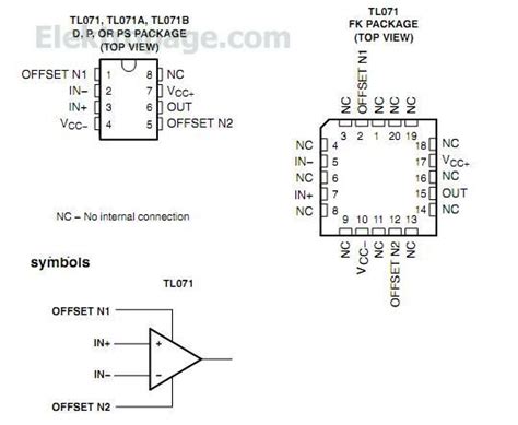
TL072 Pinout Diagram
          ___  ___
       1 |   \/   | 8
 OUT A---|+ /  -  |--- V+
       2 |  \     | 7
  -IN A--|- /    -|--- OUT B
       3 |  \     | 6
  +IN A--|+  \    |--- -IN B
       4 |    \   | 5
     V- -|_______\|--- +IN B
The TL072 comes in an 8-pin DIP (Dual Inline Package) or SOIC (Small Outline Integrated Circuit) package. The pinout consists of the following:
| Pin | Function | Description |
|---|---|---|
| 1 | OUT A | Output of op-amp A |
| 2 | -IN A | Inverting input of op-amp A |
| 3 | +IN A | Non-inverting input of op-amp A |
| 4 | V- | Negative supply voltage |
| 5 | +IN B | Non-inverting input of op-amp B |
| 6 | -IN B | Inverting input of op-amp B |
| 7 | OUT B | Output of op-amp B |
| 8 | V+ | Positive supply voltage |
Specifications
The TL072 offers the following key specifications:
| Parameter | Value |
|---|---|
| Supply Voltage Range | ±5V to ±18V |
| Input Offset Voltage | 3 mV (typ) |
| Input Bias Current | 65 pA (typ) |
| Input Impedance | 10^12 Ω |
| Gain-Bandwidth Product | 3 MHz (typ) |
| Slew Rate | 13 V/μs (typ) |
| Output Current | ±30 mA (min) |
| Input Common-Mode Voltage Range | V- + 4V to V+ – 4V |
| Operating Temperature Range | -40°C to +85°C |
These specifications make the TL072 suitable for a wide range of analog applications requiring low noise, high input impedance, and good bandwidth.
Applications
1. Audio Systems
The TL072’s low noise and high input impedance make it an excellent choice for audio applications. It can be used in:
- Preamplifiers
- Equalizers
- Active filters
- Mixing consoles
Example: Active Low-Pass Filter
An active low-pass filter using the TL072 can be designed using the following schematic:
            +------+-----+
            |      |     |
Vin ---R1---+--+   |     |
            |  |   |     |
            |  R2  | TL072
            |  |   |     |
            +--+---+--+  |
               |      |  |
               C1     |  |
               |      |  |
               +----+-+  |
                    |    |
                   GND   |
                         |
                        Vout
The cut-off frequency (fc) of this low-pass filter is given by:
fc = 1 / (2π * R2 * C1)
2. Instrumentation
The TL072’s low input bias current and high input impedance make it suitable for instrumentation applications, such as:
- Signal conditioning
- Sensor amplification
- Data acquisition systems
Example: Non-Inverting Amplifier for Sensor Signal Conditioning
A non-inverting amplifier using the TL072 can be used to amplify and condition sensor signals:
           +----+--+
           |    |  |
Vin ---R1--+--+ |  |
           |  | |  |
           |  +-+  |
           |  R2   |
           |       |
           +---+---+
               |
              GND
The gain (Av) of this non-inverting amplifier is given by:
Av = 1 + (R2 / R1)
3. Control Systems
The TL072 can be used in control systems for:
- Proportional-Integral-Derivative (PID) controllers
- Servo amplifiers
- Motor drivers
Example: Integrator for PID Controller
An integrator using the TL072 can be designed using the following schematic:
            +---+--+
            |   |  |
Vin ---R1---+--+  |
            |      |
            |      |
            |      |
            C1     |
            |      |
            +------+
The output voltage (Vout) of this integrator is given by:
Vout = -(1 / (R1 * C1)) * ∫ Vin dt

Maintenance and Troubleshooting
To ensure optimal performance and longevity of the TL072 in your circuits, consider the following maintenance and troubleshooting tips:
- Ensure proper power supply decoupling by using ceramic capacitors close to the IC’s supply pins.
- Avoid exceeding the maximum supply voltage and input common-mode voltage range to prevent damage to the device.
- Use appropriate ESD (Electrostatic Discharge) protection measures when handling the TL072.
- If experiencing oscillations or instability, consider adding a small capacitor (e.g., 10-100 pF) in parallel with the feedback resistor to provide compensation.
- Verify the correct pinout connections and supply voltages if the circuit is not functioning as expected.
Frequently Asked Questions (FAQ)
-
Q: Can the TL072 be used with single-supply operation?
A: Yes, the TL072 can be used with single-supply operation, provided that the input and output signals are properly biased within the supply voltage range. -
Q: What is the difference between the TL072 and the TL082?
A: The TL072 and TL082 are similar Dual Op-amps, but the TL082 offers a higher slew rate and gain-bandwidth product, making it more suitable for faster applications. -
Q: Can the TL072 be used as a comparator?
A: While the TL072 can be used as a comparator in some cases, it is not designed specifically for this purpose. Dedicated comparator ICs, such as the LM339, are more suitable for comparator applications. -
Q: How can I reduce the input offset voltage of the TL072?
A: To reduce the input offset voltage, you can use the offset null pins (if available) or implement an external offset nulling circuit using a potentiometer. -
Q: What is the maximum supply current drawn by the TL072?
A: The typical supply current drawn by the TL072 is around 2.4 mA per op-amp, but it can vary depending on the operating conditions and the specific device.
In conclusion, the TL072 pinout and its specifications make it a versatile choice for various analog applications, including audio systems, instrumentation, and control systems. By understanding the pinout, properly designing your circuits, and following maintenance and troubleshooting guidelines, you can effectively utilize the TL072 in your projects and ensure optimal performance.


Leave a Reply