What is the TIP122 Transistor?
The TIP122 is a high-voltage, high-current NPN Darlington transistor. A Darlington pair essentially consists of two bipolar transistors connected in a cascade configuration, giving it a very high current gain. This allows the TIP122 to switch large currents using a relatively small input current, making it ideal as an interface between low-power control circuits and high-power loads.
Some key features of the TIP122 include:
- High DC current gain (hFE) of 1000 minimum at 3A
- Can switch up to 5A continuous collector current
- 100V maximum collector-emitter voltage
- Integrated protection diode for inductive load driving
- Low 1V saturation voltage at 3A
- TO-220 through-hole package
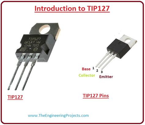
Tip122 Pinout and Pin Functions
The TIP122 comes in the common TO-220 package with three pins:
| Pin Number | Pin Name | Description |
|---|---|---|
| 1 | Base | Base of the Darlington transistor. A small current into the base controls the larger collector current. |
| 2 | Collector | Collector of the Darlington transistor. Connect this pin to the positive side of the load. |
| 3 | Emitter | Emitter of the Darlington transistor. Connect this pin to ground or the negative side of the load. |
Additionally, the metal tab of the TO-220 package is electrically connected to the Collector pin. This allows for efficient heat dissipation when the TIP122 is mounted on a heatsink.

How to Use the TIP122
Using the TIP122 is fairly straightforward. Follow these steps to control a load with the TIP122:
-
Connect the Emitter (pin 3) to ground or the negative side of your power supply.
-
Connect your load between the positive supply voltage and the Collector (pin 2). If driving an inductive load like a motor or relay, place a flyback diode in parallel with the load, cathode on the Collector side.
-
Apply a control signal to the Base (pin 1) through a current-limiting resistor. When the base-emitter voltage (VBE) exceeds about 2.5V, the transistor will turn on and current will flow through the load. Typically a 1k-10k resistor works well for logic level inputs.
-
To switch the transistor off, pull the Base voltage low (e.g. connect to ground).
Here is a basic circuit showing how to control a load with a microcontroller GPIO pin:
        MCU GPIO
           |
          +-+
          | |
         [1k]
          | |
          +-+
           |
     +-----+-----+
     |     |     |
     |  TIP122   |
     |     |     |
     | B   C     |
    (1)   (2)    |
     |     |     |
     +-----+-----+
           |
           +-----------+
           |           |
          +-+         +++
          | |         | |
          | |  Load   | |
          | |         | |
          +-+         +-+
           |           |
          GND         GND
When the GPIO is driven high, it supplies base current to the TIP122 through the 1k resistor, turning the transistor on and energizing the load. When the GPIO is low, base current is cut off and the transistor turns off.

TIP122 Protection Diode
One very useful feature of the TIP122 is its integrated protection diode between the Collector and Emitter. This diode is reverse biased during normal operation. However, when driving inductive loads like relays or motors, a high voltage spike can occur when the load is switched off due to the collapsing magnetic field. The protection diode gives this current a safe path to dissipate, preventing damage to the transistor. Always keep the diode reverse biased by connecting the Collector to the positive side of your load.

Power Dissipation and Heatsinking
The TIP122 is capable of dissipating a fair amount of power, but care must be taken not to exceed its limits. The key parameter to watch is the maximum collector-emitter voltage (VCE), which is 100V. Exceeding this voltage can cause the transistor to break down.
Power dissipation is highest when the transistor is in the linear region, i.e. not fully on or off. The power dissipated is the product of the collector current and VCE. For example, with a 12V supply switching a 3A load, the worst-case dissipation when the transistor is half-on (VCE=6V) would be:
P = I * V
= 3A * 6V
= 18W
This exceeds the 2W power dissipation the TIP122 is rated for without a heatsink. So for high power applications, always use a heatsink and ensure the transistor has adequate cooling. The metal tab of the TO-220 package allows easy mounting to a heatsink.
Example Applications
The TIP122 is a workhorse transistor that can be used in countless applications. Some common uses include:
-
Relay driver: The high current gain of the TIP122 allows even small microcontrollers to control large relays. Remember to use a flyback diode.
-
Motor driver: Brushed DC motors can be controlled with a TIP122, with PWM applied to the Base for speed control. Use a protection diode.
-
LED driver: High-power LEDs or LED strips can be switched with a TIP122. Use a current-limiting resistor in series with the LEDs.
-
Solenoid valve control: Many industrial control applications use the TIP122 to switch solenoid valves for pneumatic or hydraulic systems.
-
Audio amplifier: The TIP122 can be used as the final stage of a Class-B audio amplifier, providing high current gain and low distortion.
Frequently Asked Questions
Q: Can the TIP122 be used with 5V logic?
A: Yes, the TIP122 can be driven directly from 5V logic pins. Its minimum VBE for saturation is 2.5V, safely below 5V.
Q: How much current can the TIP122 switch?
A: The maximum continuous collector current is 5A, provided adequate heatsinking is used. The peak current is 8A.
Q: Is the TIP122 suitable for fast switching applications?
A: The TIP122 is relatively slow, with a maximum operating frequency around 10kHz. For faster switching, consider a MOSFET.
Q: Can I parallel multiple TIP122s for more current?
A: Yes, TIP122s can be paralleled to increase current capacity. Use separate base resistors and ensure each transistor has its own heatsink.
Q: What happens if I exceed the maximum VCE of the TIP122?
A: Exceeding the 100V maximum collector-emitter voltage can cause the transistor to enter breakdown, leading to excessive current and likely destroying the device. Always stay within the rated voltage.
Conclusion
The TIP122 is an incredibly useful transistor to have in your parts bin. Its high current gain, inbuilt protection diode, and robust TO-220 package make it suitable for a wide range of hobbyist and industrial switching applications. By understanding the TIP122 pinout and its features, you can use it to easily and reliably interface low-power control circuits with high-power loads. Always remember to operate the device within its specified voltage and current limits, and use a heatsink for high power dissipation. With the TIP122, you have a go-to transistor for powering all kinds of projects.


Leave a Reply