Introduction
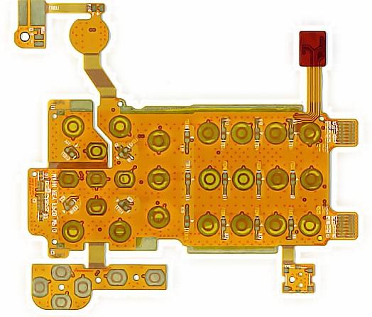
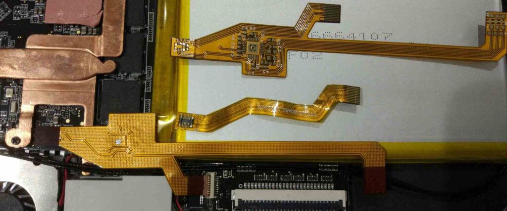
Flexible printed circuits (FPCs) are widely used in modern electronics due to their ability to bend and flex to fit constrained spaces. Proper stack-up design and analysis is critical for FPCs to ensure reliable performance under bending and dynamic stress. This article provides an overview of key considerations and best practices for FPC stack-up design.
Stack-up Configuration

The stack-up refers to the sequence and materials used in the layered construction of the FPC. Key factors to consider include:
Layer Count
The number of conductive layers (copper traces) and dielectric layers will impact flexibility, thickness, and cost. 2-layer FPCs are common, but higher layer counts allow more complex routing.
Dielectric Materials
Common materials include polyimide (PI), polyethylene terephthalate (PET), and polyethylene naphthalate (PEN). Key properties are stiffness, thermal expansion, dielectric constant, and cost. PI offers the best flex life but is more expensive than PET.
Copper Foil Type
Rolled annealed copper foils are commonly used. Electrodeposited foils are also used for finer features. Foil thickness typically ranges from 1/2 oz (17 μm) to 2 oz (70 μm). Thinner foils allow tighter bending radii.
Adhesives
Acrylic, epoxy, or thermoplastic adhesives are used to bond the copper foils to dielectric layers. Stiff adhesives reduce flex life.
Stiffeners
Metal stiffeners may be added for cable sections that do not require flexing. Stiffeners prevent buckling and improve flex circuit robustness.
Bend Radius
The minimum bend radius is a critical parameter for FPC stack-up design. Bending beyond this radius can fracture copper traces and damage dielectric layers. The minimum bend radius is impacted by:
- Copper foil thickness: Thinner copper allows tighter bending
- Dielectric material and thickness
- Number of conductive layers
- Adhesion system used
Typical minimum bend radii range from 2-10 times the total FPC thickness for multilayer boards. Suppliers can provide bend radius recommendations.
Bend Radius Example
| FPC Stackup | Thickness | Min Bend Radius |
|---|---|---|
| 2-layer, 1/2 oz CU, 25 μm PI | 0.08 mm | ~1 mm |
| 6-layer, 1/2 oz CU, 50 μm PI | 0.22 mm | ~4 mm |
Flexible Circuits vs. Rigid-Flex
For circuits requiring both flexible and rigid sections, a rigid-flex design may be used. This allows flexible “hinges” to connect rigid circuit boards. The rigid sections provide sturdiness while enabling dynamic flexing of the overall assembly.
Stack-up Analysis
To ensure reliable performance, the FPC stack-up configuration must be analyzed with respect to:
Mechanical Stress
FEA analysis of bending stress and fatigue life. Key factors are layer materials, thicknesses, and adhesion systems.
Electrical Performance
Analyze dielectric material properties, copper thickness, and trace dimensions to ensure impedance, crosstalk, and propagation delay meet requirements.
Thermal Analysis
Determine if thermal loads require heat spreaders or other provisions to prevent overheating.
FPC Layout Considerations

In addition to the stack-up, the circuit layout must also be optimized for flexing conditions:
- Avoid 90 degree bends
- Use curved traces and teardrop pads
- Anchor traces periodically using tie-downs
- Provide strain relief cutouts at flexing areas
- Minimize components in high flex areas
FPC Stack-up Design Process
A typical FPC stack-up design process involves:
- Define circuit performance and mechanical requirements
- Select dielectric and copper foil materials
- Determine layer count
- Specify minimum bend radius and flex life needs
- Iterate stack-up design and analyze per above criteria
- Verify stack-up with prototyping and testing
- Finalize stack-up configuration
FPC Materials and Constructions
Typical materials and constructions used in FPC stack-ups include:
Dielectric Films
| Material | Description | Key Properties |
|---|---|---|
| Polyimide (PI) | Most common FPC dielectric | High flex life, temp resistant |
| Polyethylene Terephthalate (PET) | Low cost alternative to PI | Lower flex life than PI |
| Polyethylene Naphthalate (PEN) | High temp resistance | Used for LCD displays |
Copper Foil
| Type | Description | Thickness Range |
|---|---|---|
| Rolled Annealed | Standard FPC copper foil | 1/2 oz (17 μm) to 2 oz (70 μm) |
| Electrodeposited | Very thin foils | As low as 3 μm |
Bonding Films
| Material | Description |
|---|---|
| Acrylic | Low cost, moderate bond strength |
| Epoxy | Higher bond strength, more brittle |
| Thermoplastic | Re-workable bonds |
FPC Production and Testing
Once the stack-up is finalized, prototypes are built and then tested to validate the design. Testing may include:
- Visual inspection
- Electrical continuity
- Insulation resistance
- Peel strength
- Bend radius verification
- Environmental stress testing
If testing reveals issues, the stack-up may need further optimization before full production.
Applications of FPCs
Due to their flexibility, FPCs are widely used in the following applications:
- Consumer electronics (laptops, mobile devices)
- Automotive and aerospace systems
- Medical devices
- Industrial equipment
- Military systems
For small form-factor and wearable devices, FPCs allow circuitry to conform to the mechanics and layouts demanded by ever-shrinking products.
Conclusion
Developing the optimal stack-up configuration is essential for flexible PCBs to meet the mechanical and electrical requirements of dynamic flexing circuits. Careful analysis of the layer materials, geometries, and performance characteristics is needed to create a robust, reliable FPC capable of meeting the demands of the application. Suppliers can provide recommendations, but ultimately the stack-up must be modeled and prototyped to validate the design. With sound stack-up engineering practices, FPCs can excel in the growing range of flex circuit applications.
FQA
What are some key differences between rigid PCB and FPC stack-ups?
Some key differences include:
- FPCs use flexible dielectric materials like polyimide instead of rigid FR4
- FPCs require dielectric and copper materials optimized for dynamic flexing
- Adhesion systems are critical for flex life in FPCs
- FPC stackups focus more on mechanical analysis like bending stress
- FPC layouts must incorporate flex-friendly design rules
Are there any limitations on component mounting with FPCs?
Yes, there are some limitations:
- Components in high flex zones should be minimized
- Components must be able to handle flexing mechanical stress
- Adhesives must be flexible and resistant to fatigue
- Smaller/thinner components are preferred to maintain flexibility
- Some components like connectors may need strain relief
What are some key considerations for FPC bend radius?
Some key considerations for bend radius include:
- Number of conductive layers
- Copper foil thickness (thinner allows tighter bending)
- Dielectric material and thickness
- Stiffness of adhesive used
- Whether stiffeners are used
- Expected number of flex cycles needed
What are some best practices for FPC layout?
Some best practices include:
- Avoid 90 degree bends
- Use teardrop pads and rounded traces
- Anchor traces periodically with tie-downs
- Provide strain relief cutouts at flexing areas
- Place components in rigid areas instead of flex areas when possible
- Follow supplier guidelines for bend radius and trace spacing
How is performance validated after assembling the FPC stack-up?
Typical testing performed includes:
- Visual inspection for defects
- Electrical continuity and insulation resistance
- Bond strength through peel or pull tests
- Microsectioning to inspect layer alignment
- Bend radius verification
- Environmental stress testing for flex life
- Electrical parameter testing for impedance, etc.
This testing validates the FPC design and production quality before full ramp-up to production.


Leave a Reply