Introduction
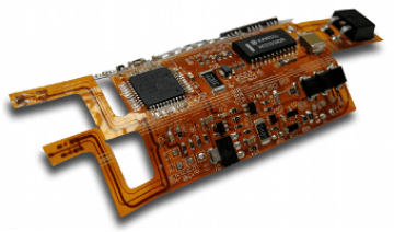
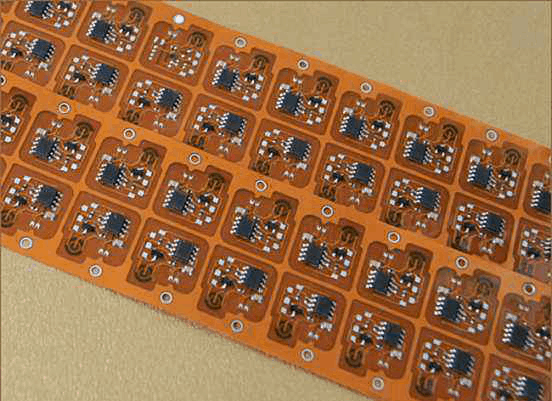
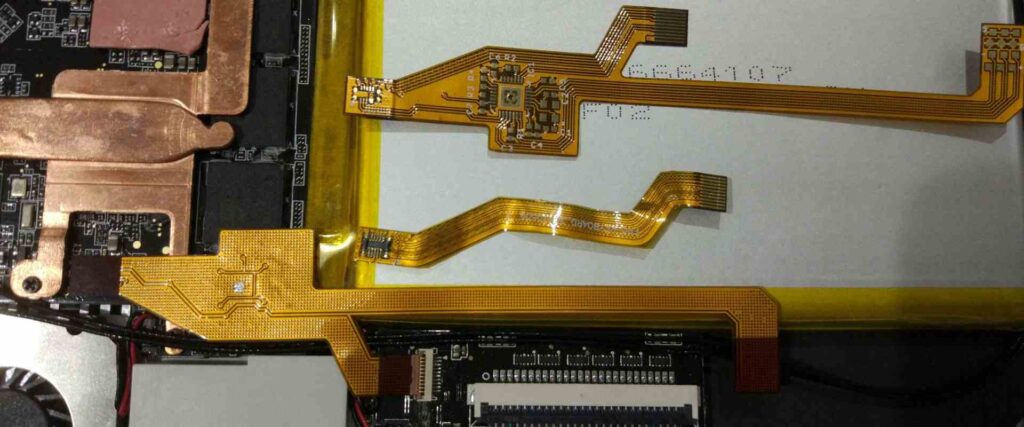
Flexible printed circuit boards (PCBs), also known as flex circuits, are increasingly being used in modern electronics due to their many advantages. As opposed to rigid PCBs, flex circuits can bend and flex to accommodate limited space and allow movement. Common applications include consumer electronics, medical devices, automotive electronics, aerospace, and industrial equipment.
However, working with and soldering flexible PCBs requires some specialized techniques and considerations. This comprehensive guide covers everything you need to know about soldering flex circuits successfully.
Benefits of Flexible PCBs
Before jumping into soldering methods, let’s first understand why flex circuits are gaining so much popularity:
- Space savings: Flexible PCBs can be folded and bent to fit into tight spaces where rigid boards won’t work. This allows for smaller and more compact product designs.
- Weight reduction: With the ability to use thinner base materials, flex circuits are much lighter in weight than rigid PCBs. This is advantageous in aerospace, automotive and portable electronics.
- Vibration dampening: The flexibility of the PCB dampens vibrations and shocks that can damage solder joints. This improves reliability and durability.
- Simplified assembly: Flex circuits allow the PCB to be pre-bent and shaped for automated assembly. Parts can also be pre-soldered onto the flex PCB.
- Enhanced reliability: Flexible PCBs withstand frequent flexing better than rigid boards and are less prone to cracking and fracturing over time.
- Cost savings: By reducing assembly steps, hardware, and downtime, flex circuits can significantly lower manufacturing costs.
Challenges of Soldering Flex Circuits
Soldering flexible PCBAs requires great care as the boards can be easily damaged if proper techniques are not followed. Here are some key challenges to be aware of:
- Warping and distortion: The thin flexible material is prone to warping and distortion when exposed to high heat. This can lift pads and traces off the board.
- Pad lifting: Excessive heat can delaminate the copper pads and traces from the base material leading to lifted pads.
- ** fracturing:** Flexing the board during soldering can cause conductor traces to fracture and break.
- Overheating components: Components on the flex board are also vulnerable to damage from excessive heat exposure during soldering.
- Limited stiffness: The lack of stiffness makes handling and processing flex circuits more difficult. Fixtures and support may be required.
- Contamination: Flexible PCBs are prone to contamination from fingerprints and oils. This must be cleaned prior to soldering.
Soldering Equipment
Having the right soldering tools is critical for flex PCB work. Here is the recommended equipment:
- Soldering iron: Use a temperature controlled solder station. Adjustable temperature in the 650-700°F range allows optimization for specific jobs.
- Tips: Fine conical or chisel shaped tips in the 0.5mm – 1mm size are best for flex circuits. Larger tips increase chances of pad lifting.
- Solder: For hand soldering, a no-clean rosin core solder in 0.015″ diameter is recommended. This reduces risks of solder bridging.
- Flux: Liquid no-clean flux aids in heat transfer and wetting, and prevents oxidation. It is typically applied using a brush.
- Magnification: Optical magnification aids in inspection and enhances precision. Get a stereo zoom microscope or magnifying glasses.
- Fume extraction: Absorb fumes generated during soldering using a solder fume extractor placed near the work area.
- Cleaning supplies: Have isopropyl alcohol, lint-free swabs, wipes, and other cleaning tools available.
Flex Circuit Handling Precautions
- Avoid touching the solder pads and traces. Only handle boards by the edges using finger cots or nitrile gloves.
- Never flex the board back and forth – this can fracture traces.
- Prevent contamination by only handling cleaned boards with finger cots.
- Use meticulous care when plugging and unplugging connectors on the flex board.
- Avoid component placement close to fold lines or high movement areas.
- Store and transport flex boards in ESD bags before and after soldering.
Soldering Techniques
With the right tools and handling procedures, soldering flexible PCBs can be accomplished successfully. Here are key techniques to follow:
Preparation
- Thoroughly clean the board using isopropyl alcohol to remove oils, dust and residues.
- Apply liquid flux on solder pads using a flux brush. This activates the pads.
- Use an oven to bake the board for 1 hour at 105°C if the board permits. This removes moisture.
- Allow the board to cool down to room temperature before soldering.
- Have a foam base or soft board under the flex circuit to support it during soldering.
Heat Application
- Keep the soldering iron tip clean and free of residual solder. Wet the tip with fresh solder.
- Use the lowest temperature possible for soldering. Temperatures above 700°F risk pad lifting.
- Heat joints as briefly as possible, for no longer than 2 seconds at a time.
- Simultaneously heat the component lead and solder pad to form the joint.
- Avoid directly heating the flex board material. Heat only the solder joint area.
- Apply heat evenly on both sides of polarized components to prevent thermal shock.
Solder Application and Removal
- Use fine gauge solder wire to prevent solder bridging between joints.
- Apply the soldering iron to heat the joint, and then add the solder wire to the joint.
- Use desoldering braid to remove excess solder. Do not tug or pull on the flexible board material.
Post Soldering
- Let the board cool down fully to room temperature before handling.
- Carefully inspect solder joints under magnification for defects like cracks or cold joints.
- Reapply flux and reheat any questionable joints.
- Avoid repeated cycles of soldering, cooling, and reheat as this increases thermal stress.
- Coat the board with conformal coating for corrosion protection if required.
Board Support
- Place the flex board over a foam base or use clamps to support it during soldering.
- For small boards, tape down sections not being actively soldered.
- Larger boards may need stiffeners or frames to prevent sagging and warping from gravity.
- Use circuit board holders to securely grip boards and position as required.
Common Soldering Defects
Inspecting for and identifying soldering defects is an important part of working with flex circuits. Here are some common issues:
Cold joints – Identified by a rough darkened surface or weakened bond between surfaces. Cause is insufficient heat being applied to the joint area during soldering.
Cracked joints – Hairline cracks through the solder joint. Generally caused by flexing or vibration during cooling. Can lead to conductivity issues.
Solder bridges – Unintended solder material between adjacent pads or tracks, causing shorts. Use of too much solder or large tip causes bridging.
Lifted pads – Pad is separated from the base laminate due to excess heat damaging the adhesive. Seen as an elevated pad.
Solder voids – Gas pockets within the solder joint, reducing mechanical strength. Due to low solder temperature or contaminated/oxidized surfaces.
Icicle formation – Jagged spike-like solder protrusions caused by solder rapidly solidifying before wetting occurs. Use smaller tip and lower temperature.
Distortion – Twisting, warping or stretching of the flex board. Results from uneven heating or handling during soldering process.
FQA
What temperature should be used to solder flex circuits?
For hand soldering flex boards, ideal tip temperature is 650°F to 700°F. Higher temperatures increase the chances of overheating and pad lifting defects. Operator skill is also a key factor.
Can flex PCBs be soldered using reflow or wave soldering?
Yes, both reflow and wave soldering can be used for flex PCBs, provided process controls are implemented to prevent thermal shock. Pre-heating is essential, and the number of passes should be minimized.
How can pads be prevented from lifting during hand soldering?
Use minimum required soldering temperature, clean tips, fine gauge solder, and simultaneous heating of pad and lead. Avoid excessive dwell time. Also maintain firmly supported boards and use conformal coating.
Why do conformal coatings help when soldering flex circuits?
Conformal coatings provide mechanical support to the flex board, strengthen solder joints, and reduce the effects of board bending and vibration that can crack joints.
How are components with leads soldered on flex PCBs?
Leaded components are soldered by bending the leads to align with pads, solder tacking one side first, visually inspecting alignment, then soldering the other side. This prevents stressing the board.
Conclusion
Flexible printed circuit boards provide many advantages for space constrained and portable electronics designs. However hand soldering flex circuits requires meticulous care and the use of proper techniques to prevent damaging the flexible material.
With the right soldering tools, controlled heating, and board handling procedures, reliable solder joints can be produced on flex PCBAs. Taking precautions like cleaning, fluxing, supporting the board, and inspecting joints prevents common defects like cracking and lifted pads.
As flex-rigid PCBs utilizing both flexible and rigid sections become more popular, many of these same practices will also apply to soldering the flex areas of those boards. With some experience, electronics assemblers can become proficient at soldering flexible PCBs and harnessing their benefits.


Leave a Reply