Over the past few decades, electronics have become smaller, lighter, and more portable. Simultaneously, they are packing in more features and capabilities. This trend towards miniaturization and higher functionality is enabled by advances in semiconductor packaging, assembly techniques, and printed circuit board (PCB) technology. One key PCB technology innovation has been the development of rigid-flex PCBs, which integrate rigid and flexible circuitry into a single structure.
What is Rigid-Flex PCB?
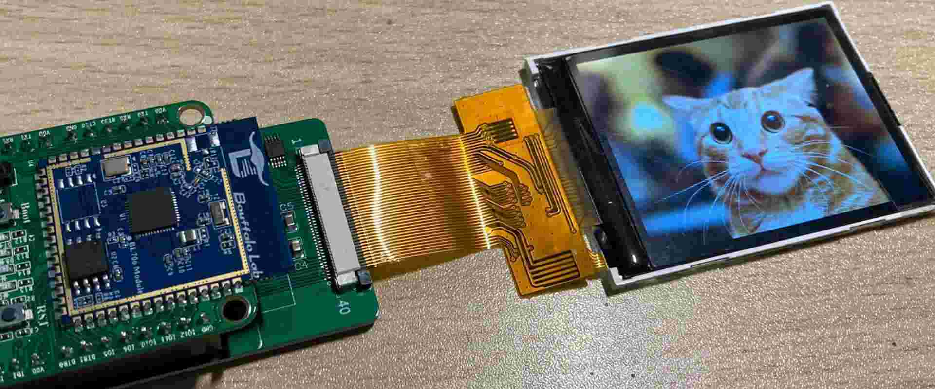
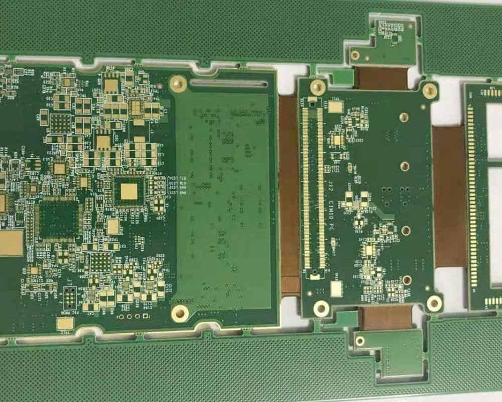
A rigid-flex PCB (also known as rigid-flex, flex-rigid, or flex PCB) combines rigid and flexible circuit boards. This allows the PCB to maintain the structure and stability of a rigid PCB but fold and flex like a flexible circuit. Rigid-flex PCBs provide solutions for three-dimensional, space and weight constrained electronics packages.
The rigid sections of the PCB provide mechanical support and leverage conventional PCB manufacturing processes. The flexible sections allow the rigid sections to bend and fold to fit into housings and packages. Flexible circuits also enable interconnections between multiple rigid boards. Matching the coefficient of thermal expansion between rigid and flexible materials is critical to ensure reliability across temperature fluctuations.
Benefits of Rigid-Flex PCBs
Rigid-flex PCBs provide a number of benefits over conventional rigid PCBs:
- Miniaturization – By folding and wrapping circuits into three-dimensional structures, rigid-flex PCBs enable smaller and thinner products. Removing connectors between rigid boards saves space.
- Increased Reliability – Eliminating interboard connectors improves reliability by reducing the number of mechanical and electrical interfaces. Circuits are also protected from dust and vibration.
- Higher Speeds – Shorter electrical paths in flexible circuits enable higher speed signals and higher frequency circuits. Impedance control is easier with thin, tightly spaced traces.
- Design Flexibility – Rigid-flex allows creative industrial design and ergonomic product packaging not feasible with planar rigid boards. Circuits can be shaped around other components.
- Lower Assembly Costs – Reducing connectors lowers component count and simplifies assembly. Automated soldering and inspection is also simplified.
- Lower Weight – Thin polyimide-based flex circuits weigh less than rigid fiberglass boards. This enables lighter end products.
For products pushing the limits of miniaturization, reliability, speed, and packaging, rigid-flex PCB technology enables designs not possible with previous approaches. Next we’ll look at some specific applications taking advantage of rigid-flex PCBs.
Rigid-Flex PCB Applications
Rigid-flex PCBs first gained popularity in military aerospace applications in the 1960s-70s. Since then, they have spread to many commercial markets including computing, telecom, medical, industrial, and consumer electronics. Here are some examples:
Computing and Mobile Devices
Laptops, tablets, and smartphones must pack increasing functionality into ever slimmer packages. Rigid-flex PCBs fold into tight spaces and enable flexible device configurations. Specific implementations include:
- Hinges and housings wrapping around displays
- Interconnections between main logic board and I/O modules
- Antenna connections conforming to mechanical enclosures
Wearable Electronics
Wearable products need to match the contours of the human body. Rigid sections mount chips and sensors while flex circuits trace along bends and folds. Healthcare products such as hearing aids and medical sensors leverage rigid-flex technology.
Automotive Electronics
Auto manufacturers use rigid-flex PCBs to fit circuits into tight spaces and save weight. Flexible circuits withstand vibration. Specific applications include engine control units, sensors, instrument clusters, and infotainment systems.
Industrial IoT and Robotics
Connecting sensors and controls in robots and industrial equipment requires PCBs that can flex, twist, and turn. Rigid-flex allows reliable cabling in motion control systems. Circuits embedded in robot joints also use rigid-flex technology.
Defense and Aerospace
Avionics systems withstand high vibration levels over wide temperature ranges. Rigid-flex PCBs deliver proven reliability in harsh environments. Missile guidance systems, radars, and communications links leverage rigid-flex.
This list highlights the diversity of rigid-flex PCB applications across many different markets. Essentially any small, lightweight product needing to embed electronics can potentially benefit from rigid-flex PCB technology.
Design Considerations
While rigid-flex PCBs provide many benefits, they also introduce their own design considerations:
Layer Stacking: With multiple layer rigid stacks and thin flex layers, layer counts can quickly grow complex. Careful documentation of layer thicknesses, materials, and sequences is essential.
Routing: Autorouters may have difficulty with rigid-flex designs. Manual routing across split rigid and flex sections takes planning. Maintaining high speed impedance constraints is critical.
Flex Bends: The flexible sections must be carefully designed to bend in the required directions without damaging traces. Minimum bend radius rules must be followed.
Connections: Reliable connections transitioning between rigid and flex layers are important. Soldered, clamped, or glued approaches are used.
Modeling and Simulation: Upfront modeling and analysis of electrical performance, thermal stress, vibration response, and reliability helps avoid issues during product development.
While presenting challenges, none of these considerations are showstoppers for an experienced rigid-flex PCB designer.
Rigid-Flex PCB Manufacturing
Specialized processes are required to manufacture rigid-flex PCBs:
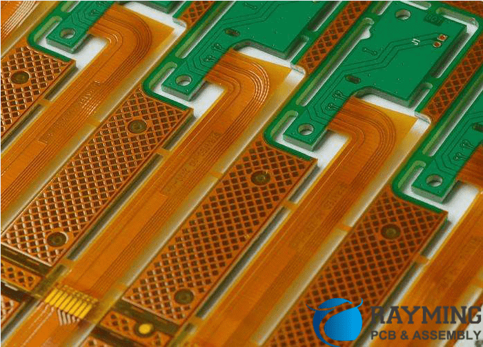
Material Selection: The rigid and flex materials must have compatible processing conditions and thermal expansion. FR-4 is commonly used for rigid sections along with polyimide or polyester films for the flex layers.
Layer Alignment: The process must provide accurate layer-to-layer alignment between the embedded flexible layers and rigid outer layers during lamination.
Via Drilling: Microvias are drilled using lasers. The via diameters match the trace widths of the thin flex layers.
Metallization: Sputtered and electroplated metals coat the flex material instead of panel plating more common for rigid boards.
Etching: Printed circuit patterning adapts from rigid board processes to appropriately etch the flexible films.
Testing: Rigid-flex PCBs require specialized fixtures to support them during functional testing. Electrical testing and inspection tools also need to handle combination rigid and flex circuits.
Scoring and Folding: The rigid sections are scored or routed to create fold lines. The boards are precisely bent and folded into the 3D configurations.
Assembly: Parts are assembled on the exposed top and bottom sides of the rigid sections using standard SMT assembly processes.
While requiring special handling, rigid-flex manufacturing leverages many of the high-volume automation techniques used for standard PCBs.
Outlook for Rigid-Flex Technology
Rigid-flex PCBs will continue growing in adoption and popularity. The industry roadmaps forecast rigid-flex PCB production expanding at over 8% CAGR over the next decade.
The performance requirements for electronics also continue advancing. 5G communications, autonomous vehicles, IoT sensors, and wearables will rely on advanced PCB technologies. Rigid-flex enables the sophisticated PCB solutions needed for these next-generation products.
In summary, rigid-flex PCB technology will be even more pervasive in the future. It enables the innovative and miniature products defining the modern marketplace. Rigid-flex PCBs deliver the speed, reliability, and packaging these cutting-edge devices demand.
Frequently Asked Questions
What are the key benefits of rigid-flex PCBs?
The main benefits are miniaturization, improved reliability, higher speeds, flexible industrial design, lower assembly costs, and reduced weight. Rigid-flex PCBs fold into tight spaces, eliminate connectors, enable high-speed signals, and conform to product shapes.
What products use rigid-flex PCBs?
Many markets use rigid-flex PCBs including consumer electronics, computing and mobile devices, wearables, automotive, aerospace, industrial, and medical products. Any lightweight, compact product needing to embed electronics can potentially utilize rigid-flex technology.
What are the main design considerations with rigid-flex PCBs?
Complex layer stacking, routing across split sections, accounting for flex bends, managing layer connections, and modeling/simulation are key design considerations for rigid-flex PCBs. An experienced rigid-flex designer understands how to address these challenges.
How are rigid-flex PCBs manufactured?
Specialized materials, layer alignment during lamination, microvia drilling, metal coating processes, etching procedures, fold scoring, and assembly fixtures are used to fabricate a rigid-flex PCB. Many standard PCB manufacturing techniques are adapted to handle combination rigid and flexible circuits.
What is the future outlook for rigid-flex PCBs?
Rigid-flex PCBs are forecasted to grow steadily in adoption and use. Their ability to meet the demands of miniaturization, high reliability, and advanced packaging will lead to increased usage in consumer electronics, automotive, aerospace, medical, and industrial applications.


Leave a Reply