What is a Rigid-Flex PCB?
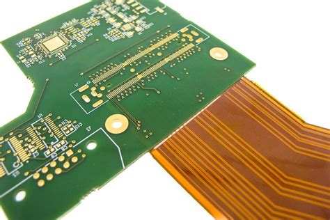
A Rigid-Flex PCB, also known as a Rigid-Flex Circuit or a Flex-Rigid PCB, is a unique type of printed circuit board that combines the best features of both rigid and flexible PCBs. It consists of multiple layers of flexible PCB substrate interspersed with rigid PCB sections, allowing for a highly customizable and adaptable circuit design.
The flexible portions of the board are made from thin, flexible materials such as polyimide or polyester, while the rigid sections are constructed using standard FR-4 or other rigid PCB materials. The combination of these materials enables the creation of a circuit that can bend, fold, or twist in specific areas while maintaining the structural integrity and reliability of a traditional rigid PCB.
Advantages of Rigid-Flex PCBs
Rigid-Flex PCBs offer several advantages over traditional PCBs, making them an attractive choice for a wide range of applications. Some of the key benefits include:
-
Space Savings: By combining rigid and flexible sections, Rigid-Flex PCBs can be designed to fit into tight spaces and conform to unique product shapes, reducing the overall size and weight of the device.
-
Improved Reliability: The flexible portions of the PCB allow for greater stress relief and better resistance to vibration and shock, enhancing the overall reliability of the circuit.
-
Reduced Assembly Costs: Rigid-Flex PCBs can eliminate the need for connectors and cables between rigid boards, simplifying the assembly process and reducing overall costs.
-
Enhanced Signal Integrity: The elimination of connectors and the ability to control impedance in the flexible sections can lead to improved signal integrity and reduced electromagnetic interference (EMI).
-
Design Flexibility: Rigid-Flex PCBs offer designers greater freedom to create unique, three-dimensional layouts that would be impossible with traditional rigid boards.
Applications of Rigid-Flex PCBs
Rigid-Flex PCBs are used in a variety of industries and applications where space constraints, reliability, and design flexibility are critical factors. Some common applications include:
-
Aerospace and Defense: Rigid-Flex PCBs are well-suited for aerospace and defense applications, where high reliability, space savings, and resistance to harsh environmental conditions are essential.
-
Medical Devices: The ability to create compact, reliable circuits makes Rigid-Flex PCBs ideal for medical devices such as wearables, implantables, and diagnostic equipment.
-
Consumer Electronics: Rigid-Flex PCBs are increasingly used in consumer electronics, such as smartphones, tablets, and laptops, to enable thinner, lighter, and more feature-rich designs.
-
Automotive: As vehicles become more technologically advanced, Rigid-Flex PCBs are being used in applications such as infotainment systems, driver assistance features, and vehicle networking.
-
Industrial Automation: Rigid-Flex PCBs can withstand the harsh conditions and demanding requirements of industrial automation applications, such as robotics, process control, and data acquisition systems.
Rigid-Flex PCB Design Considerations
Designing a Rigid-Flex PCB requires careful consideration of several factors to ensure optimal performance, reliability, and manufacturability. Some key design considerations include:
1. Material Selection
Choosing the right materials for your Rigid-Flex PCB is crucial for achieving the desired performance and reliability. Factors to consider when selecting materials include:
- Dielectric Constant (Dk) and Dissipation Factor (Df): These properties affect signal integrity and power loss, respectively. Materials with low Dk and Df values are generally preferred for high-speed designs.
- Thermal Expansion: Mismatches in the coefficient of thermal expansion (CTE) between rigid and flexible materials can lead to stress and reliability issues. Choosing materials with similar CTEs can help minimize these problems.
- Flexural Endurance: For applications that require repeated flexing, it’s essential to choose materials with high flexural endurance to ensure long-term reliability.
Some common flexible substrate materials include polyimide, polyester, and flexible epoxy, while rigid sections typically use FR-4, high-Tg FR-4, or polyimide laminates.
2. Stack-up Design
The stack-up design of a Rigid-Flex PCB plays a critical role in determining its electrical performance, mechanical stability, and manufacturability. When designing the stack-up, consider the following:
- Layer Count: Determine the number of layers needed for both rigid and flexible sections based on the complexity of the circuit and the required functionality.
- Copper Thickness: Choose appropriate copper thicknesses for each layer based on current carrying requirements and signal integrity considerations.
- Adhesive Layers: Select suitable adhesive materials and thicknesses to ensure proper bonding between layers and to minimize the impact on electrical performance.
- Shielding: Incorporate shielding layers as needed to reduce EMI and improve signal integrity.
3. Flexible Circuit Routing
Routing the flexible portions of a Rigid-Flex PCB requires special considerations to ensure reliability and prevent damage during flexing. Some guidelines for flexible circuit routing include:
- Bend Radius: Ensure that the minimum bend radius of the flexible circuit is within the manufacturer’s specifications to avoid excessive stress and potential failure.
- Trace Width and Spacing: Use appropriate trace widths and spacing to minimize stress concentration and improve flexibility. Wider traces and larger spacing are generally recommended for flexible sections.
- Strain Relief: Incorporate strain relief features, such as curved traces or mechanical supports, to reduce stress at the rigid-flex interface and improve reliability.
4. Rigid-Flex Interface Design
The interface between rigid and flexible sections is a critical area that requires careful design to ensure reliability and manufacturability. Some considerations for rigid-flex interface design include:
- Staggered Rigid-Flex Transitions: Use staggered transitions between rigid and flexible layers to distribute stress and minimize the risk of delamination or cracking.
- Coverlay and Stiffener Placement: Strategically place coverlay and stiffeners to protect the flexible circuit and provide additional support in high-stress areas.
- Anchoring: Properly anchor the flexible circuit to the rigid sections using techniques such as plated through-holes, surface mount pads, or mechanical fasteners to ensure a secure connection.
5. Manufacturing Considerations
Designing a Rigid-Flex PCB with manufacturability in mind is essential for ensuring a smooth and cost-effective production process. Some manufacturing considerations to keep in mind include:
- Panelization: Organize the Rigid-Flex PCBs on the manufacturing panel in a way that optimizes material usage, minimizes waste, and facilitates easy depanelization.
- Tolerances: Work closely with your manufacturer to understand their capabilities and specify appropriate tolerances for critical features such as hole sizes, line widths, and spacing.
- Testing and Inspection: Plan for appropriate testing and inspection steps throughout the manufacturing process to ensure quality and catch any issues early in the production cycle.

Rigid-Flex PCB Manufacturing Process
The manufacturing process for Rigid-Flex PCBs is more complex than that of traditional rigid PCBs due to the integration of flexible and rigid materials. The general steps involved in the manufacturing process are as follows:
-
Material Preparation: The flexible and rigid substrate materials are cut to size and cleaned to remove any contaminants.
-
Lamination: The flexible and rigid layers are laminated together using heat and pressure, with adhesive layers placed between them to ensure proper bonding.
-
Drilling: Holes are drilled through the laminated board for plated through-holes, vias, and other features.
-
Plating: The drilled holes are plated with copper to create electrical connections between layers.
-
Patterning: The copper layers are patterned using photolithography and etching processes to create the desired circuit traces and features.
-
Solder Mask and Silkscreen: A solder mask is applied to protect the copper traces, and silkscreen markings are added for component placement and identification.
-
Coverlay and Stiffener Application: Coverlay and stiffeners are applied to the flexible portions of the PCB to provide protection and support.
-
Outline Routing: The individual Rigid-Flex PCBs are routed out of the manufacturing panel using a mechanical router or laser cutter.
-
Surface Finishing: The exposed copper areas are coated with a surface finish, such as ENIG (Electroless Nickel Immersion Gold) or OSP (Organic Solderability Preservative), to protect the copper and enhance solderability.
-
Electrical Testing: The completed Rigid-Flex PCBs undergo electrical testing to ensure they meet the specified performance requirements and are free of defects.
Throughout the manufacturing process, strict quality control measures are implemented to ensure the highest level of reliability and performance in the final product.

Rigid-Flex PCB Assembly Techniques
Assembling components onto a Rigid-Flex PCB requires specialized techniques to accommodate the unique characteristics of the flexible substrate. Some common assembly techniques used for Rigid-Flex PCBs include:
1. Surface Mount Technology (SMT)
SMT is the most common assembly method for Rigid-Flex PCBs, as it allows for the placement of components on both the rigid and flexible sections of the board. The general SMT assembly process involves:
- Solder Paste Application: Solder paste is applied to the SMT pads using a stencil or syringe.
- Component Placement: Components are placed onto the solder paste using pick-and-place machines or by hand.
- Reflow Soldering: The assembled board is passed through a reflow oven, which melts the solder paste and forms a permanent electrical and mechanical connection between the components and the PCB.
2. Flexible Circuit Soldering
For components that need to be attached directly to the flexible portions of the PCB, special soldering techniques are required to prevent damage to the delicate substrate. Some common flexible circuit soldering methods include:
- Hand Soldering: Manual soldering using a fine-tipped soldering iron and low-temperature solder can be used for small components or low-volume assembly.
- Hot Bar Soldering: A heated bar is used to press the component leads onto the flexible circuit pads, melting the solder and forming a connection. This method is well-suited for flat pack or ribbon cable connections.
- Laser Soldering: A focused laser beam is used to heat the solder and form a connection between the component and the flexible circuit. This method offers high precision and minimal heat exposure to the substrate.
3. Adhesive Bonding
In some cases, components may be attached to the flexible circuit using adhesive bonding instead of soldering. This method is often used for mounting non-solderable components or for providing additional mechanical support. Common adhesive bonding techniques include:
- Conductive Epoxy: A conductive epoxy is used to form an electrical and mechanical connection between the component and the flexible circuit.
- Anisotropic Conductive Film (ACF): An ACF is placed between the component and the flexible circuit, and heat and pressure are applied to form a connection through the conductive particles in the film.
4. Stiffener Mounting
Stiffeners are often used to provide additional support and protection for components mounted on the flexible sections of the PCB. Stiffeners can be attached using adhesive bonding or mechanical fasteners, depending on the specific requirements of the application.
When assembling components onto a Rigid-Flex PCB, it’s essential to follow best practices for handling and processing to minimize the risk of damage to the flexible substrate and ensure reliable connections.

Rigid-Flex PCB Testing and Inspection
Thorough testing and inspection are critical for ensuring the quality, reliability, and performance of Rigid-Flex PCBs. Some common testing and inspection methods used for Rigid-Flex PCBs include:
1. Visual Inspection
Visual inspection is the first line of defense in identifying potential issues with a Rigid-Flex PCB. This process involves carefully examining the board for any visible defects, such as:
- Misaligned or missing components
- Solder bridges or insufficient solder
- Damaged or delaminated flexible circuits
- Incorrect component placement or orientation
Visual inspection can be performed manually or using automated optical inspection (AOI) systems for higher-volume production.
2. Continuity and Isolation Testing
Continuity and isolation testing are used to verify that the electrical connections on the Rigid-Flex PCB are correct and that there are no short circuits or open connections. This testing can be performed using:
- Flying Probe Testing: A set of movable probes is used to test the continuity and isolation of each net on the PCB.
- Fixture-Based Testing: A custom-designed test fixture with spring-loaded pins is used to make contact with the test points on the PCB, allowing for rapid testing of the entire board.
3. Functional Testing
Functional testing involves verifying that the assembled Rigid-Flex PCB performs as intended in its end-use application. This testing may include:
- Power-On Testing: Verifying that the board powers up correctly and that all components receive the proper voltage and current.
- Signal Integrity Testing: Measuring the quality of the signals transmitted through the board to ensure they meet the specified requirements.
- Environmental Testing: Subjecting the board to various environmental conditions, such as temperature cycling, humidity, and vibration, to ensure it can withstand the expected operating conditions.
4. X-Ray Inspection
X-ray inspection is a non-destructive testing method that allows for the examination of solder joints and other internal features of the Rigid-Flex PCB. This method is particularly useful for inspecting:
- Ball Grid Array (BGA) solder joints
- Plated through-holes and vias
- Buried or hidden components
X-ray inspection can help identify issues such as voids, cracks, or insufficient solder that may not be visible through other inspection methods.
5. Microsectioning
Microsectioning is a destructive testing method that involves cross-sectioning a sample of the Rigid-Flex PCB and examining it under a microscope. This method is used to verify the internal structure of the board, including:
- Layer alignment and registration
- Copper plating thickness and uniformity
- Adhesion between layers
- Proper formation of plated through-holes and vias
Microsectioning is typically performed on a small sample of boards from each production run to ensure consistent quality and adherence to manufacturing specifications.
By implementing a comprehensive testing and inspection plan, manufacturers can identify and address any issues with Rigid-Flex PCBs before they reach the end-user, ultimately improving the overall quality and reliability of the final product.
Frequently Asked Questions (FAQ)
-
Q: What is the difference between a Rigid-Flex PCB and a traditional rigid PCB?
A: A Rigid-Flex PCB combines both rigid and flexible substrates into a single, integrated circuit board. This allows for greater design flexibility, improved reliability, and reduced space requirements compared to traditional rigid PCBs. -
Q: What are the main advantages of using a Rigid-Flex PCB?
A: The main advantages of using a Rigid-Flex PCB include space savings, improved reliability, reduced assembly costs, enhanced signal integrity, and greater design flexibility. -
Q: What industries commonly use Rigid-Flex PCBs?
A: Rigid-Flex PCBs are commonly used in industries such as aerospace, defense, medical devices, consumer electronics, automotive, and industrial automation, where space constraints, reliability, and design flexibility are critical factors. -
Q: What are some key design considerations for Rigid-Flex PCBs?
A: Key design considerations for Rigid-Flex PCBs include material selection, stack-up design, flexible circuit routing, rigid-flex interface design, and manufacturing considerations, such as panelization, tolerances, and testing. -
Q: How does the manufacturing process for Rigid-Flex PCBs differ from that of traditional rigid PCBs?
A: The manufacturing process for Rigid-Flex PCBs is more complex than that of traditional rigid PCBs due to the integration of flexible and rigid materials. The process involves additional steps such as lamination, coverlay, and stiffener application, as well as specialized techniques for drilling, plating, and routing.
Conclusion
Rigid-Flex PCBs offer a unique and powerful solution for applications that require a combination of design flexibility, reliability, and space savings. By integrating both rigid and flexible substrates into a single, integrated circuit board, Rigid-Flex PCBs enable the creation of highly customized and efficient electronic devices across a wide range of industries.
However, designing and manufacturing Rigid-Flex PCBs requires careful consideration of various factors, such as material selection, stack-up design, flexible circuit routing, and rigid-flex interface design. Adhering to best practices and working closely with experienced Rigid-Flex PCB manufacturers can help ensure the success of your project.
As technology continues to advance and the demand for more compact, reliable, and feature-rich electronic devices grows, the use of Rigid-Flex PCBs is expected to continue expanding. By understanding the unique characteristics, advantages, and design considerations of Rigid-Flex PCBs, engineers and product designers can leverage this powerful technology to create innovative and high-performance products that meet the needs of an ever-evolving market.


Leave a Reply