What is a Rigid-Flex PCB?
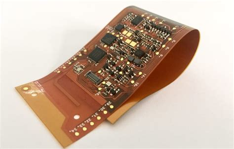
A rigid-flex PCB is a printed circuit board that combines both rigid and flexible substrates, allowing the board to be bent and folded to fit into tight spaces or unique enclosures. The rigid areas of the board provide structural support for components, while the flexible regions enable the board to conform to the shape of the device or to be folded for more compact packaging.
Advantages of Rigid-Flex PCBs
Rigid-flex PCBs offer several advantages over traditional rigid PCBs:
- Space savings: By folding the flexible regions, rigid-flex PCBs can fit into smaller spaces, reducing the overall size of the device.
- Reduced weight: Rigid-flex PCBs eliminate the need for connectors and cables between rigid sections, reducing the overall weight of the assembly.
- Improved reliability: With fewer interconnects and connectors, rigid-flex PCBs have fewer potential points of failure, improving overall reliability.
- Enhanced signal integrity: The continuous copper traces in the flexible regions minimize signal loss and interference compared to separate rigid boards connected by cables.
- Design flexibility: Rigid-flex PCBs allow for more creative and efficient packaging designs, as the board can be shaped to fit the device’s form factor.
Designing Rigid-Flex PCBs
Layer Stackup
A typical rigid-flex PCB layer stackup consists of alternating layers of rigid and flexible materials. The rigid layers are usually made of FR-4, while the flexible layers are made of polyimide or other flexible substrates. Copper traces are etched onto both rigid and flexible layers, with plated through-holes connecting the layers electrically.
| Layer | Material | Thickness |
|---|---|---|
| Top Cover | Polyimide | 0.05mm |
| Top Copper | Copper | 0.035mm |
| Flexible Core | Polyimide | 0.05mm |
| Bottom Copper | Copper | 0.035mm |
| Bottom Cover | Polyimide | 0.05mm |
| Rigid Layer 1 | FR-4 | 0.2mm |
| Rigid Layer 2 | FR-4 | 0.2mm |
Bend Radius and Flex Zones
When designing rigid-flex PCBs, it is essential to consider the bend radius and the placement of flex zones. The bend radius is the minimum radius that the flexible region can be bent without damaging the copper traces or the substrate. The bend radius depends on the thickness of the flexible layers and the copper weight. A general rule of thumb is to keep the bend radius at least 10 times the total thickness of the flexible region.
Flex zones should be placed in areas where the board will be bent or folded. It is important to avoid placing components or vias in the flex zones, as they can cause stress on the copper traces and lead to fatigue or failure over time.
Component Placement and Routing
When placing components on a rigid-flex PCB, it is best to locate them on the rigid sections of the board. This provides a stable surface for soldering and helps to minimize stress on the components during bending. If components must be placed on flexible regions, use smaller, low-profile components and consider using adhesives to secure them to the substrate.
Routing traces on rigid-flex PCBs requires careful consideration of the bend zones and the stress on the copper traces. In the flexible regions, traces should be routed perpendicular to the bend line to minimize stress. Avoid sharp angles or abrupt changes in trace direction, as these can create stress concentrations and lead to fatigue or failure.

Manufacturing Rigid-Flex PCBs
Materials Selection
Choosing the right materials is critical for the success of a rigid-flex PCB design. The flexible substrate must be able to withstand repeated bending without cracking or delaminating. Polyimide is the most common choice for flexible substrates due to its excellent mechanical and electrical properties. For the rigid sections, FR-4 is the standard material, although other materials like aluminum or ceramic may be used for specific applications.
Copper weight is another important consideration. Thinner copper layers are more flexible but have higher resistance and may not be suitable for high-current applications. Thicker copper layers have lower resistance but are less flexible and may require a larger bend radius.
Fabrication Process
The fabrication process for rigid-flex PCBs is more complex than for traditional rigid PCBs. The process involves laminating the rigid and flexible layers together, drilling and plating through-holes, and etching the copper traces. The flexible regions are then cut out and the rigid sections are routed to shape.
One critical aspect of the fabrication process is the adhesion between the rigid and flexible layers. Poor adhesion can lead to delamination and failure of the board. To ensure good adhesion, the surfaces of the rigid and flexible layers must be properly treated and cleaned before lamination.
Testing and Inspection
Rigid-flex PCBs require thorough testing and inspection to ensure reliability and functionality. In addition to standard electrical tests like continuity and insulation resistance, rigid-flex PCBs must also undergo mechanical tests to verify the integrity of the flexible regions.
One common test is the bend test, where the flexible regions are repeatedly bent to a specified radius to simulate real-world use. The board is then inspected for signs of damage or delamination. Other tests may include thermal cycling, vibration, and shock testing, depending on the application.

Applications of Rigid-Flex PCBs
Rigid-flex PCBs are used in a wide range of applications where space is limited, and reliability is critical. Some common applications include:
- Aerospace and defense: Rigid-flex PCBs are used in avionics, satellites, and military equipment where size and weight are critical factors.
- Medical devices: Wearable medical devices, implantable devices, and surgical instruments often use rigid-flex PCBs to fit into small, complex shapes.
- Consumer electronics: Smartphones, tablets, and wearable devices use rigid-flex PCBs to maximize space efficiency and enable innovative form factors.
- Automotive: Rigid-flex PCBs are used in vehicle control modules, sensors, and infotainment systems where vibration and temperature extremes are common.
- Industrial equipment: Robotics, machine vision systems, and automation equipment use rigid-flex PCBs for their reliability and ability to fit into tight spaces.

FAQ
1. What is the difference between a rigid-flex PCB and a flex PCB?
A rigid-flex PCB combines both rigid and flexible substrates in a single board, while a flex PCB is made entirely of flexible materials. Rigid-flex PCBs offer the advantages of both rigid and flexible boards, providing structural support and flexibility where needed.
2. Can rigid-flex PCBs be repaired?
Repairing rigid-flex PCBs can be challenging due to the complex structure and the presence of both rigid and flexible regions. In most cases, it is more cost-effective to replace a damaged rigid-flex PCB rather than attempting to repair it.
3. How long do rigid-flex PCBs last?
The lifespan of a rigid-flex PCB depends on several factors, including the materials used, the design, and the application environment. With proper design and manufacturing, rigid-flex PCBs can last for many years, even in demanding applications like aerospace and medical devices.
4. Are rigid-flex PCBs more expensive than traditional rigid PCBs?
Yes, rigid-flex PCBs are typically more expensive than traditional rigid PCBs due to the more complex manufacturing process and the use of specialized materials. However, the cost is often offset by the space and weight savings, improved reliability, and design flexibility offered by rigid-flex PCBs.
5. Can rigid-flex PCBs be used in high-temperature applications?
Yes, rigid-flex PCBs can be designed for high-temperature applications by using appropriate materials and design techniques. Polyimide, for example, has a high glass transition temperature and can withstand temperatures up to 260°C. However, the maximum operating temperature of a rigid-flex PCB will depend on the specific materials and components used in the design.
Conclusion
Rigid-flex PCBs offer a unique combination of structural support and flexibility, enabling designers to create more compact, lightweight, and reliable electronic devices. By understanding the design considerations, manufacturing processes, and applications of rigid-flex PCBs, engineers can take advantage of this innovative technology to streamline their designs and improve product performance.
As the demand for smaller, more complex electronic devices continues to grow, rigid-flex PCBs will play an increasingly important role in enabling the next generation of products. With proper design and manufacturing, rigid-flex PCBs can provide a reliable, cost-effective solution for a wide range of applications, from aerospace and medical devices to consumer electronics and industrial equipment.


Leave a Reply