Introduction to Rigid-Flex PCBs
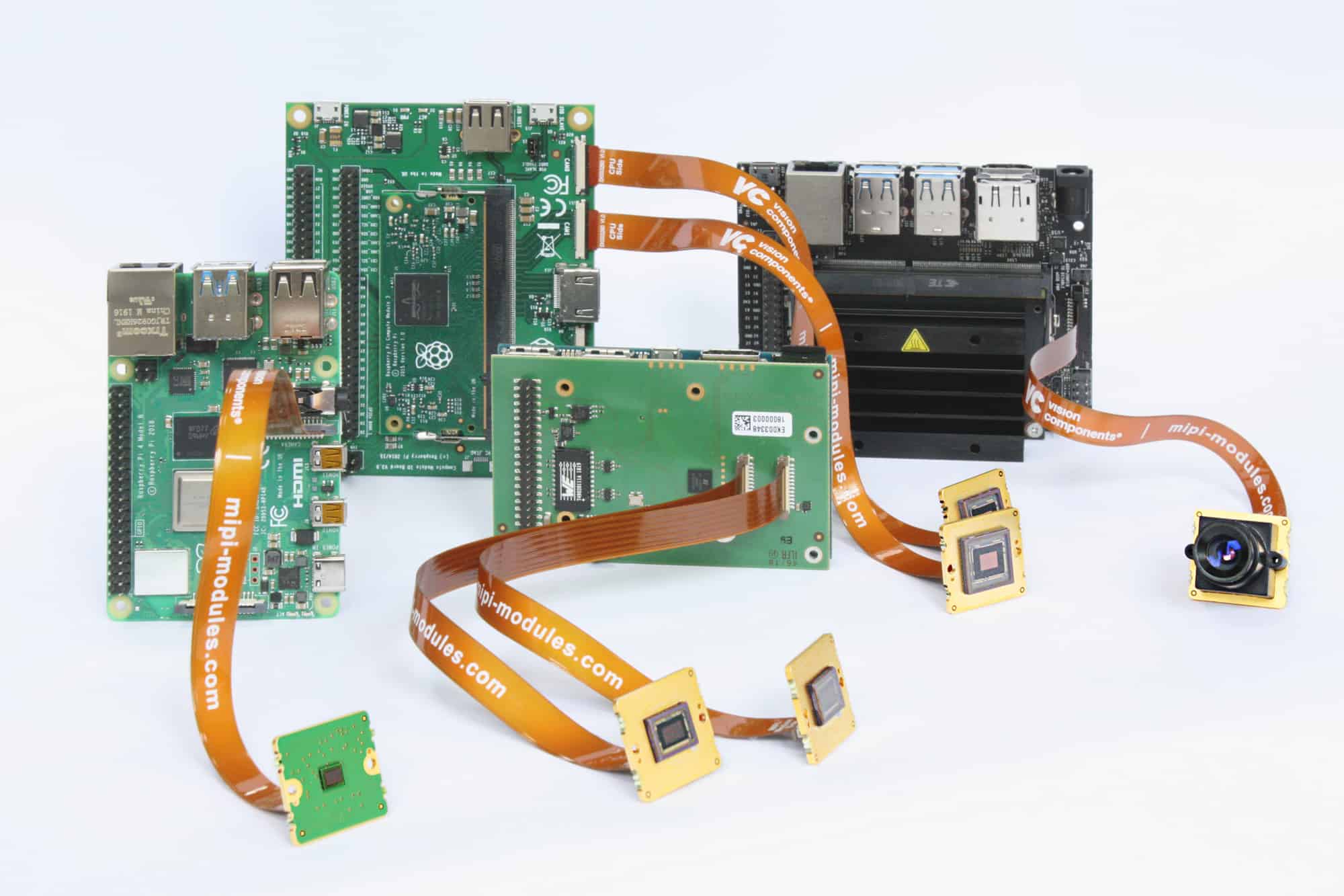
Rigid-flex PCBs, also known as flex-rigid PCBs or flex circuits, combine rigid and flexible circuit boards into a single assembly. They provide solutions for applications that require:
- Dynamic flexing or movement
- Space and weight savings
- Three-dimensional configuration
- High density interconnections
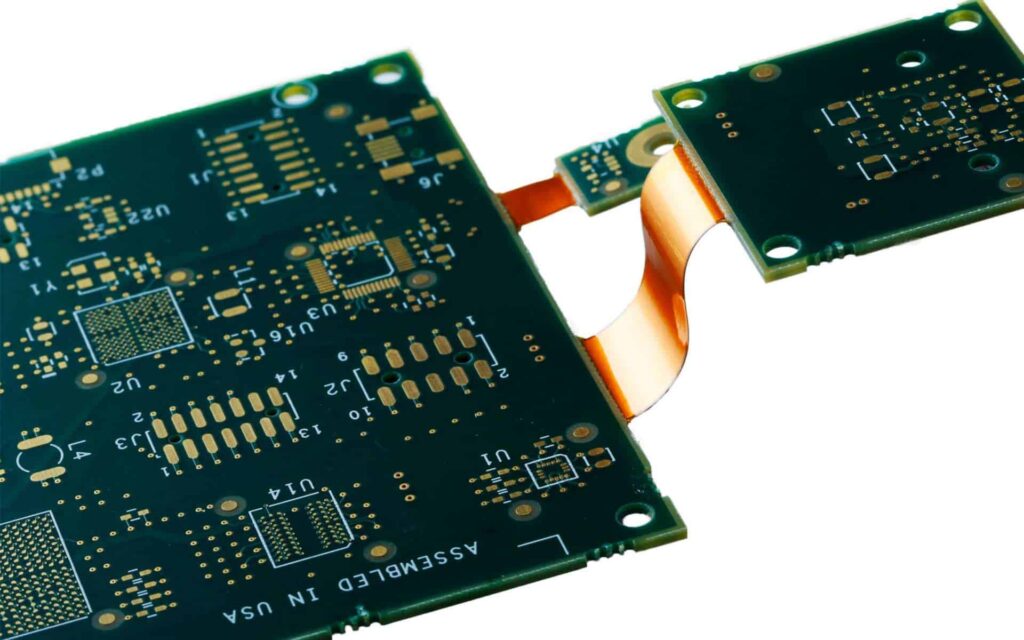
Rigid-flex PCBs allow the rigid sections to provide mechanical support and mounting surfaces, while the flex sections interconnect the rigid boards and provide flexing. This enables compact, lightweight, and highly reliable electronic packages.
Advantages of Rigid-Flex Designs
Here are some of the key advantages rigid-flex PCBs offer:
- Space savings: By folding and bending, rigid-flex PCBs fit into tight spaces and provide more layout options. They eliminate wires and connectors between boards.
- Flexibility: The flex sections allow motion and dynamic flexing where needed. Products can be designed to be more ergonomic and portable.
- Reliability: Rigid-flex PCBs have fewer connectors compared to assembling separate rigid PCBs. This results in lower failure rates and improved shock/vibration resistance.
- Weight reduction: Eliminating wires and connectors significantly reduces weight. This is critical in aerospace, military, and portable consumer devices.
- Enhanced functionality: Rigid-flex allows greater freedom in positioning components across both rigid and flex sections. More functionality can be packed into a constrained space.
In summary, rigid-flex PCBs enable thinner, lighter, and more reliable electronic designs with enhanced flexibility and functionality. The ability to fold and embed a flex circuit within a product opens new possibilities in packaging.
Rigid-Flex Construction and Materials
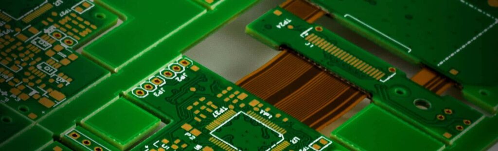
There are several ways to construct rigid-flex PCBs depending on the application requirements. Here are the main elements that go into a rigid-flex build:
- Rigid sections – Usually standard FR-4 material, but sometimes high-frequency or thermal boards are used.
- Flexible sections – Made of polyimide or other flexible polymer materials. Thickness around 2 mils.
- Bonded sections – Where the rigid and flex layers are joined with adhesive.
- Cover layers – Additional polyimide layers protecting the flex layer conductor traces.
- Stiffeners – Added to strengthen and control flex sections.Can be copper or acrylic.
- Cutouts and windows – Openings in the rigid sections to allow bending of the flex layer.
In terms of materials, the rigid portions would use standard FR-4 or other rigid PCB materials. The flexible substrate is usually polyimide (Kapton®), but PET and PEN films can also be used.
Fabrication Process
Rigid-flex PCBs require specialized fabrication. Here is a general process overview:
- Rigid layers and flexible layers are processed separately, including imaging, developing, and etching.
- Holes are drilled or laser-ablated in the rigid sections where flexing is needed.
- Layers are carefully aligned and laminated using adhesive and heat.
- Final through-hole plating, routing, and solder masking steps are completed.
- Electrical testing validates the design prior to shipment.
The process requires advanced skills in alignment, bonding, registration, and handling thin flexible materials. Most PCB manufacturers use dedicated rigid-flex lines or processes.
Rigid-Flex Design Guidelines
Here are some key design considerations for rigid-flex PCB layout:
- Determine required layers beforehand as changes later are difficult
- Plan spacing between rigid sections to allow room for flex bending
- Use teardrop shaped cutouts in rigid sections for flex transition
- Avoid 90 degree bends; use large radius rounded corners instead
- Design flex layer length to width ratio at least 2:1 to prevent twisting
- Minimize components in the rigid/flex transition areas
- Plan stiffener locations to control flex area movement
- Use coverlayers, solder mask, or Kapton tape for flex insulation
- Eliminate copper near fold areas to prevent cracking
- Watch trace widths and spacing in the thin flex layers
- Plan panel utilization to match production processes
Following established design rules and DFx guidelines is critical to avoiding rigid-flex fabrication issues. Consult closely with your PCB manufacturer early in the design process.
Dynamic vs. Static Flex
An important concept in rigid-flex design is dynamic vs. static flex.
- Dynamic flexing: Continuous or frequent flexing motions, like folding/unfolding or repeated adjustments. Requires extensive testing to prevent metal and copper fatigue.
- Static flexing: One-time bend or curve to shape, such as wrapping a board around a product enclosure. Fewer fatigue concerns.
Dynamic rigid-flex designs require more engineering effort to ensure the circuits can withstand extensive repeated bending cycles. Work closely with the PCB fabricator on the design to ensure reliable functionality.
Rigid-Flex Applications
Rigid-flex PCBs have been implemented successfully across many industries and applications, including:
| Industry | Example Applications |
|---|---|
| Consumer Electronics | Cell phones, laptops, cameras, wearables |
| Medical | Hearing aids, IV monitoring devices, blood analyzers |
| Military/Defense | Guided missiles, avionics systems, radars |
| Industrial | Robotics, automation controllers, instrumentation |
| Transportation | Automotive sensors and controls, trains, UAVs |
Some specific rigid-flex implementation examples include:
- Cell phone antennae, hinges, and flex connections between boards
- Wearable health monitor curving around the body
- Battery packs with rigid battery slots and interconnects
- Hinge allows tablet display to fold over the keyboard
- Aerospace optics folding into the body of the plane
The flex portions provide the motion, shape conformance, and 3D configuration needed, while maintaining integral connections with the rigid PCBs containing components.
Benefits in Various Applications
Here are some of the major benefits realized in different product applications:
Portable Electronics
- Tight interconnections between PCBs without cables
- Dynamic flexing to protect delicate solder joints from fatigue
- Folding into compact size for smaller product enclosures
Medical Devices
- Static flexing to route board around human body
- Elimination of wires improves reliability and durability
- Lighter weight compared to rigid boards
Military/Aerospace
- Withstands vibration/shock compared to connectors between boards
- Reduces weight which is crucial for air and spacecraft
- Allows flexible snaking through compact compartments
Automotive
- Static flexing to conform to vehicle shapes
- Connect devices like cameras and sensors with one assembly
- Reduce cabling allows simpler and lower cost installation
As you can see, rigid-flex PCBs provide size, weight, reliability, and flexibility improvements across many application areas. The benefits multiply as products continue getting smaller and more connected.
Partnering with a Rigid-Flex PCB Manufacturer
Developing a reliable rigid-flex design requires an experienced PCB manufacturer. Here are some tips on selecting a good partner:
- Make sure they have expertise specifically in rigid-flex PCBs – this is a specialty process compared to regular PCB fabrication. Ask details about their specific rigid-flex capabilities.
- Review examples of previous rigid-flex projects they have produced, preferably in your industry.
- Make sure they have qualified processes that are well-characterized to produce consistent quality. Ask about their process capabilities.
- Evaluate their engineering support – can they provide DFx assistance and review your design for manufacturability? Early feedback is highly valuable.
- Look for design tool integration offerings that simplify data exchange and communication.
- Choose a partner committed to continuous improvement rather than staying static. Technology keeps evolving so a cutting edge partner is beneficial.
By selecting the right rigid-flex PCB partner, you gain access to specialized knowledge and experience that will make your project go smoothly. Investing early in the relationship pays back with optimized designs, faster time-to-market, and high quality solutions.
Conclusion
Rigid-flex PCB technology provides unique solutions for increasingly complex and compact electronic products across many industries. By combining rigid board stability and flex circuit dynamism into a single assembly, rigid-flex PCBs enable smaller, lighter, and more reliable systems.
With early planning and an experienced rigid-flex PCB partner, electrical engineers can take full advantage of the benefits. Rigid-flex opens new possibilities for product industrial design that are not feasible with rigid PCBs alone. As electronic applications continue requiring advanced packaging, connectivity, and configuration, rigid-flex PCBs will take on growing importance. Partnering with an expert rigid-flex design house helps ensure you develop optimized designs that achieve your product goals.
FAQ
What are some typical layer counts for rigid-flex boards?
Rigid layers are commonly 2 to 12 layers. Flex layers are typically 1 to 4 layers. High density designs may go up to 20 layers for rigid and 8 layers for flex circuits. The total layer count includes both rigid and flex layers in the assembly.
Can components be mounted directly on the flex layer?
It is generally advised to avoid placing components directly on the thin flexible layer. The components can act as “speed bumps” during flexing and cause uneven stresses. Components are best placed on the more stable rigid portions.
What tolerances should be used for rigid-flex PCB designs?
In general, use tighter tolerances for features on the flex layers. Lines/spaces as low as 2/2 mils (0.1mm) can sometimes be achieved but require advanced processes. For rigid portions, use regular PCB fabrication tolerances.
How many bends cycles can rigid-flex boards withstand?
Dynamic flex life depends on many factors like bend radius, copper thickness, and flex layer materials. Typical cycle life ranges from 10,000 to over 1 million cycles. Rigorous testing is required to qualification number of bending cycles for a given design.
Can conventional PCB design software be used for rigid-flex boards?
Specialized rigid-flex design tools are recommended due to the unique constraints and DFM requirements. Many PCB software packages now offer advanced rigid-flex modules to assist designers. Consult your PCB fabrication partner on suggested design tools.


Leave a Reply