
Rigid flex circuits, also known as rigid flexible printed circuit boards (PCBs), are a unique type of printed circuit board that offer the benefits of both rigid and flexible PCBs. As the name suggests, rigid flex circuits consist of both rigid and flexible substrates that are laminated together into a single circuit board.
Rigid flex circuits provide mechanical support, versatility in 3D design, and reliability similar to rigid PCBs. At the same time, the flexible sections allow for dynamic flexing and bending, space and weight savings, and improved serviceability compared to flexible circuits alone. This combination makes rigid flex circuits ideal for many applications where flexibility and reliability are both critical requirements.
In this comprehensive guide, we will cover everything you need to know about rigid flex circuits, including:
Table of Contents
- What Are Rigid Flex Circuits?
- Benefits and Applications of Rigid Flex Circuits
- Rigid Flex Circuit Materials and Construction
- Rigid Flex Circuit Design Considerations
- Rigid Flex Circuit Manufacturing Process
- Rigid Flex Circuit Testing and Inspection
- Rigid Flex vs Flexible Circuits vs Rigid PCBs
- Rigid Flex Circuit Costs
- Rigid Flex Circuit Suppliers and Manufacturers
- FAQs About Rigid Flex Circuits
What Are Rigid Flex Circuits?
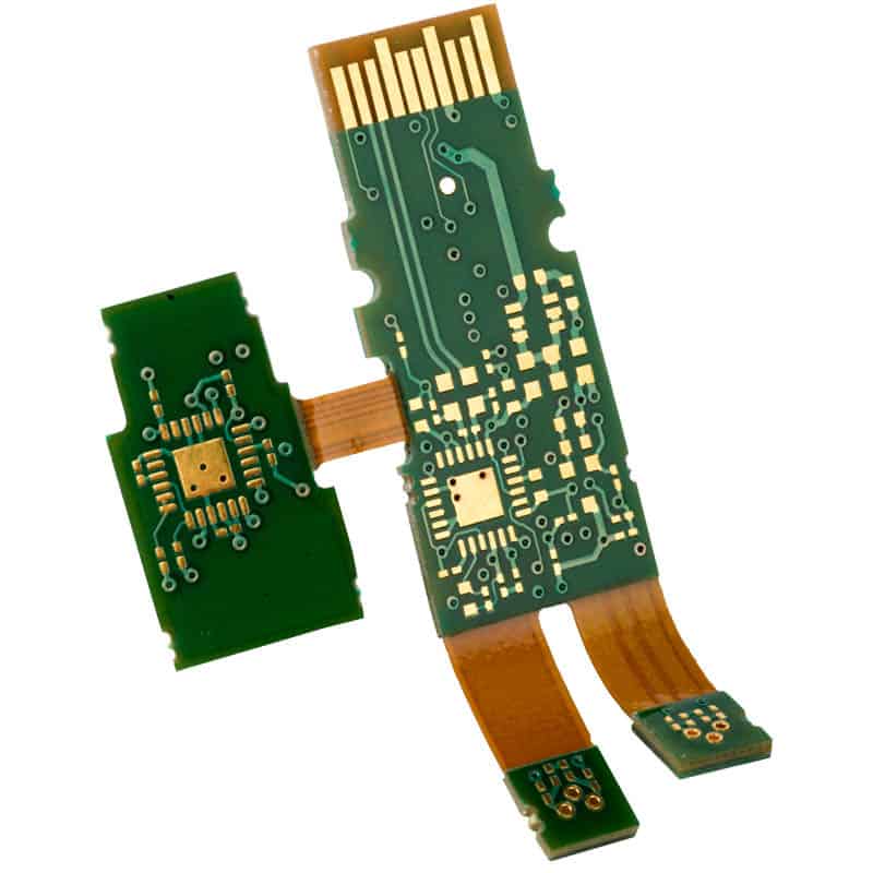
Rigid flex circuits integrate rigid and flexible materials into a single circuit board. Here are some key defining characteristics of rigid flex circuits:
- They contain both rigid sections (usually FR-4 material) and flexible sections (usually polyimide).
- The rigid and flex sections are bonded together into one integrated circuit board.
- The flexible sections allow dynamic flexing and bending without damage.
- Rigid sections provide mechanical support and rigidity where needed.
- Components can be mounted on both rigid and flexible areas.
- Rigid flex circuits come in many shapes and configurations.
- They can be single-sided, double-sided, or multilayer.
- Board thickness and number of layers may vary in rigid vs. flex sections.
In essence, rigid flex PCBs offer the benefits of two technologies – rigid PCBs and flexible circuits – in one design. The rigid sections offer support while the flexible sections allow for bending and flexing.
Benefits and Applications of Rigid Flex Circuits
There are many advantages to using rigid flex circuits instead of rigid PCBs or flexible circuits alone:
Benefits of Rigid Flex Circuits:
- Dynamic flexing and bending ability
- Reduced weight and space requirements
- Increased reliability and mechanical support
- Design versatility for complex 3D configurations
- Ability to mount components on both rigid and flex areas
- Improved serviceability in the field
- Reduced system wiring/cabling
- Enhanced thermal performance
- Lower assembly costs in some cases
These benefits make rigid flex circuits well suited for:
Applications of Rigid Flex Circuits:
- Aerospace and defense systems
- Portable medical devices
- Robotics and automation equipment
- Foldable/movable electronics
- Consumer products like cell phones
- Vehicles and transportation products
- Industrial machines and tools
- Wearable technology
- Computer peripherals
Rigid flex allows complex circuitry to fit into tight spaces that move and bend, making it an enabling technology for many advanced applications. The combination of support and flexibility is difficult to achieve with other circuit board types.
Rigid Flex Circuit Materials and Construction
Rigid flex circuits can be constructed using a number of different material combinations. Here are some of the most common options:
Rigid Sections:
- FR-4 – Glass reinforced epoxy laminate
- Polyimide – More flexible but still rigid polyimide film
- Aluminum – Thin aluminum layers or inserts
- Copper – Thin copper layers for heat spreading
Flexible Sections:
- Polyimide – Thin polyimide film such as Kapton
- PEEK – Polyether ether ketone for high temp applications
- PET – Polyethylene terephthalate for economic choice
- TPU – Thermoplastic polyurethane for extra flexibility
- PEN – Polyethylene naphthalate film
The rigid layers provide mechanical support while the flex layers allow dynamic bending and folding. The two are joined together using adhesives such as acrylic, epoxy, or polyimide bonding films.
Here are some other construction notes:
- Board thickness is typically consistent in rigid sections but varies in flexible areas.
- Flexible sections are usually very thin (1-3 mils).
- Rigid sections can be standard 1.6mm thickness.
- 4-8 layer constructions are common.
- Can be double-sided or multilayer boards.
- Flexible sections normally do not contain thru-hole vias.
Careful design of the materials and stackup is needed to withstand mechanical and thermal stresses.
Rigid Flex Circuit Design Considerations
Designing a rigid flex circuit requires some special considerations, both in the PCB layout and the mechanical design of the flexing/bending areas. Here are some key rigid flex design guidelines:
PCB Layout:
- Minimize trace lengths in flexing sections.
- Avoid sharp 90° angles on traces in flex areas.
- Use teardrop pads in flexible sections for improved reliability.
- Place components only on rigid sections, not on flexing areas.
- Watch for clearance around rigid-flex transition areas.
- Utilize special rigid-flex DRC rules and stackups.
- Analyze board level reliability factors like shock, vibration, flex cycles.
Flexible Section Design:
- Determine required bend radius and minimum flex requirements.
- Ensure adequate flexibility by controlling material selection and thickness.
- Design smooth contours and transitions at rigid-flex junctions.
- Avoid flexible sections near board edges to prevent tearing.
- Plan circuit layout and component placement for required rigid-flex folding.
- Perform advanced stress analysis on flex areas.
- Determine optimal adhesive selection and lamination process.
Careful consideration of electrical, mechanical, and manufacturing factors is needed to yield a reliable, functional rigid flex circuit.
Table 1: Recommended minimum bend radii for common flexible PCB materials
| Material | Minimum Bend Radius |
|---|---|
| Polyimide (Kapton) | 10 x Board Thickness |
| PEN | 15 x Board Thickness |
| PET | 20 x Board Thickness |
| Polyurethane | 10 x Board Thickness |
| PEEK | 15 x Board Thickness |
Proper bend radius is critical to avoid cracking and damage. The minimum bend depends on the flexible material used.
Rigid Flex Circuit Manufacturing Process
Specialized manufacturing techniques are required to produce high quality rigid flex circuits. Here is an overview of the rigid flex fabrication process:
1. CVD Copper Lamination
- Adhere thin copper foil onto rigid and flexible substrate materials
- Provides ability to pattern circuits on both sections
2. Image Transfer
- Photolithography process transfers circuit patterns onto metal layers on rigid and flex sections
3. PCB Etching
- Etch away unwanted copper to create circuit traces and pads
4. Hole Drilling
- Drill holes on rigid sections for through hole components and vias
5. Plating
- Electrolytic copper plating to plate hole walls and overlay circuitry
6. Lamination
- Bond rigid and flex materials together using adhesive films
- Requires process control to avoid flex damage
7. Final Patterning
- Additional photolithography and etching
8. Solder Mask and Silkscreen
- Apply solder mask over traces and openings at pads
- Print identifying nomenclature and symbols
9. Final Finishing
- Edge trimming, routing, contouring, electrical testing, etc.
Rigid flex manufacturing requires specialized skills, processes, and equipment. Working with an experienced rigid flex supplier is advised.
Rigid Flex Circuit Testing and Inspection
Verification testing and inspection is critical for rigid flex circuits given their unique construction. Some key test and inspection methods include:
- Visual Inspection – Check for defects under magnification
- Dimensional Inspection – Confirm trace spacing, hole sizes, etc.
- Netlist Testing – Validate circuit network connections
- Fabrication Defects – Check for common defects like opens, shorts
- Electrical Testing – Validate electrical functioning, apply test vectors
- Automated Optical Inspection (AOI) – Detect defects and anomalies
- X-Ray Inspection – Check internal layer alignment and abnormalities
- Cross-Section Analysis – Images circuit layer composition and adhesion
- Solderability Testing – Validate suitability for soldering processes
- Plating Thickness – Measure copper thickness on traces and in holes
- Flex Cycle Testing – Test ability to withstand continuous flexing
- Environmental Stress Testing – Assess impact of thermal, vibration, shock, etc.
This range of test methods helps ensure the quality and reliability of the completed rigid flex assembly.
Rigid Flex vs Flexible Circuits vs Rigid PCBs
It can be helpful to understand how rigid flex PCBs differ from common flexible circuit boards and rigid PCBs:
| Rigid Flex Circuits | Flex Circuits | Rigid PCBs | |
|---|---|---|---|
| Composition | Rigid and flexible substrates laminated together | Mostly flexible materials | Primarily rigid materials |
| Key Feature | Combines rigid stability and flexible bending | Dynamic flexing and bending | Structural support and rigidity |
| Main Applications | Aerospace, medical, automotive, etc. | Smaller wearables and interconnects | Nearly all electronics |
| Circuits Possible | Single-sided, double-sided, multilayer | Mostly 2 layer flexible boards | Wide range of layer counts |
| Component Mounting | On rigid sections only | Limited – only on flex areas | Across entire board surface |
| Common Materials | Rigid – FR4, polyimide / Flex – polyimide, PEN | Polyimide, PEN | FR4 glass epoxy |
| Manufacturability | Requires special processes | Relatively simple processing | Mature manufacturing processes |
| Cost | Moderate, can be low volume | Low cost, high volume | Lowest cost at high volumes |
So in summary, rigid flex combines strengths of both rigid boards and flex circuits for an optimal blend of support, reliability, and flexibility.
Rigid Flex Circuit Costs
As a specialty printed circuit board technology, rigid flex circuits can have higher costs than standard rigid PCBs. Here are some notes on rigid flex cost factors:
- Low to medium volume production – Smaller batches increase per unit costs
- More complex fabrication – Additional process steps required
- Advanced materials – Specialty rigid and flexible materials
- More manual labor – Not as automated as standard PCB production
- Testing overhead – Extensive inspection and reliability testing
- Complex design – Engineering time for electrical and mechanical design
- Tooling costs – For contour machining and routing
However, rigid flex costs can be lower than combining separate rigid and flex boards, due to integration benefits. Costs drop at higher volumes.
Table 2: Approximate Rigid Flex Circuit Price Ranges
| Layer Count | Complexity | Volume | Cost per Unit |
|---|---|---|---|
| 2-4 | Medium | <500 | $100 – $500 |
| 4-6 | Medium | 500-5,000 | $50 – $150 |
| 6-8 | High | 1,000-10,000 | $75 – $250 |
| 8-10 | Very High | 10,000+ | $50 – $100 |
Prices vary widely based on design complexity, layer count, order volumes, size, and other factors.
Rigid Flex Circuit Suppliers and Manufacturers
There are contract manufacturers and specialized suppliers that offer rigid flex PCB production services. Here are a few larger rigid flex circuit manufacturers:
- TTM Technologies – Large global PCB manufacturer that offers rigid-flex capabilities.
- AT&S – Austria-based company focused on advanced HDI and rigid-flex PCBs.
- Compunetics – Rigid-flex PCB designer and manufacturer located in the USA.
- Rush PCB – Prototype and small batch rigid flex provider based in the USA.
- Multek – Specializes in flexible circuits and rigid flex technology. Owned by Flex Ltd.
- ECM – Provides advanced rigid flex solutions for defense, aerospace, and other applications.
Smaller companies also offer rigid-flex PCB services, sometimes focused on prototypes and low volume orders. Working with an established rigid flex supplier helps ensure you get a high-quality PCB assembly.
FAQs About Rigid Flex Circuits
Here are some common questions and answers about rigid flex technology:
What are some alternatives to using rigid flex circuits?
Alternatives include using separate rigid and flex PCBs joined through connectors or cabling. But rigid flex allows tighter integration and miniaturization. For static applications, regular rigid PCBs may suffice.
How do you attach components to rigid flex circuits?
Components can only be assembled onto the rigid portions through soldering. Flexible areas are not suitable for component mounting.
Are rigid flex circuits suitable for high frequency, RF designs?
Yes, rigid flex can support high frequency circuits through careful stackup design and controlled dielectric properties. They offer advantages for many RF assemblies.
What are some considerations for ruggedizing rigid flex circuits?
Conformal coatings, potting compounds, metal shields, and other techniques can ruggedize rigid flex circuits for harsh environments.
Are rigid-flex PCBs expensive?
They typically cost more than rigid PCBs but offer advantages through integration and miniaturization. Costs drop significantly at production volumes.
Can rigid flex PCBs be double-sided or multilayer?
Yes, rigid flex allows for multilayer, double-sided, and even mixed constructions with different layer counts in rigid vs. flex sections.
How small can rigid flex circuits be fabricated?
Rigid flex allows very small, fine line flex circuits. Lines/spaces down to 25/25 microns are possible with controlled line width/gap.
Conclusion
Rigid flex PCB technology offers the unique combination of mechanical support from rigid sections and dynamic flexing ability from flexible sections integrated into one circuit board. Rigid flex circuits are enabling many advanced applications and devices requiring small, reliable circuitry that can bend and flex. Through careful design and manufacturing considerations, engineers can take advantage of rigid flex capabilities across a wide array of industries.


Leave a Reply