
What are Rigid-Flex Circuit Boards?
Rigid-flex circuit boards, also known as rigid-flex circuits or flex-rigid boards, are a type of printed circuit board (PCB) that consist of rigid and flexible substrates laminated together. This allows the PCB to maintain its shape while also being able to flex and bend along the flexible areas.
Rigid-flex boards provide solutions when:
- Space is limited and components need to fit into a small footprint
- Designs require dynamic flexing or motion
- Ability to mount components on both sides of the board is needed
- Reducing overall weight of the product is a priority
Some key advantages of rigid-flex boards:
- Ideal for three-dimensional circuitry and packaging
- Can improve reliability and durability with dynamic flexing
- Allows for greater component density
- Reduces overall weight and size of product
- Lower cost compared to rigid-only boards for complex designs
Rigid-flex boards are commonly used in aerospace, military, medical, and consumer electronics, but have applications across many industries.
How are Rigid-Flex Circuit Boards Constructed?
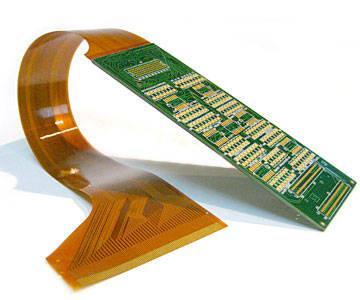
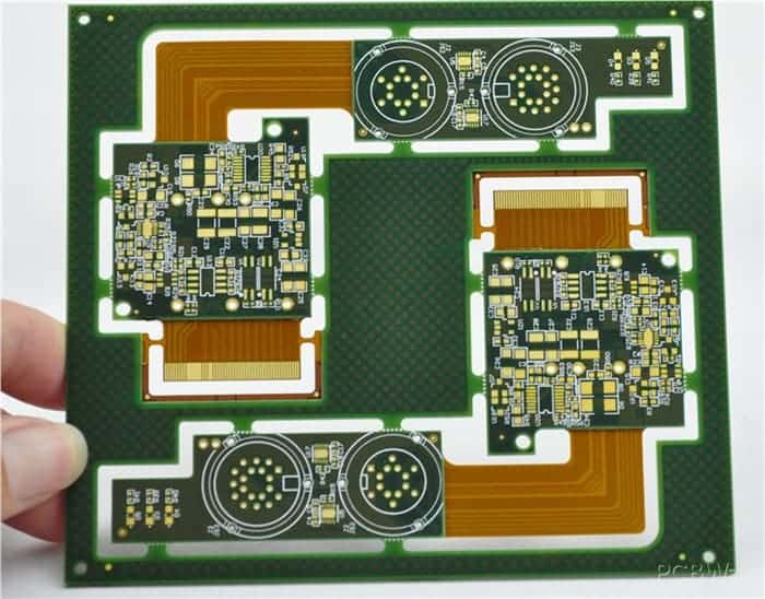
Rigid-flex boards consist of alternating sections of rigid board material and flexible polymer material that are bonded together during lamination. Here are the basic construction steps:
- Rigid sections are processed like standard PCBs with desired layer stackup. This forms the stiff backbone structure.
- Flexible sections are added by bonding thin polyimide sheets using adhesive films. These areas will bend and flex.
- Conductive traces are etched to connect rigid and flex sections. Traces follow precise contours.
- Components are assembled onto the board by soldering or adhesive.
- The finished board can be dynamically flexed and maintain high reliability.
There are a few common rigid-flex layer stackup configurations:
| Configuration | Description |
|---|---|
| 2 Layer | Single-sided flex, double-sided rigid |
| 4 Layer | Double-sided flex, double-sided rigid |
| 6+ Layer | Multilayer rigid with double-sided flex |
Rigid-Flex PCB Design Considerations
Designing a reliable rigid-flex board requires paying special attention to the following areas:
Flex Bend Radii
- Sharp flex bends can cause traces to crack or delaminate.
- Minimum bend radius depends on flex thickness. General rule of thumb is to have radius > 10x material thickness.
- Dynamic flexing limits are set by flex laminate and trace materials.
Layer Transitions
- Must transition from rigid to flex layer counts carefully.
- Common way is to taper down layers in rigid section.
- Can also incorporate rigid-flex “fingers” if needed.
Component Placement
- Avoid placing components in high flex zones.
- Distribute components evenly to prevent uneven stress.
- Use smaller, flexible surface mount components when possible.
Board Outline
- Allow sufficient rigid board support near connectors.
- Dogbone shapes can provide stress relief at transitions.
- Anchor points are needed to mount rigid sections.
Trace Routing
- Route traces efficiently to maximize flex life.
- Avoid 90° turns; use arc or 45° beveled traces instead.
- Plan for dynamic copper stress and fatigue.
Testing
- Test bending radius, flex cycle life, torsion/twist, etc.
- Ensure solder joint and component integrity.
- Vibration, drop, and shock testing often needed.
Rigid-Flex PCB Applications
Rigid-flex PCBs open up new possibilities in electrical system design. Here are some common applications that benefit from their unique advantages:
Aerospace and Defense
- Tight space requirements in aerospace benefit from 3D arrangement.
- Flexible connections between rigid boards for vibration resistance.
- Lightweight compared to cabling for onboard electronics.
Medical Electronics
- Bendable circuits to fit ergonomic medical devices.
- Dynamic flex life for wearables, implants.
- Aid miniaturization of instruments and testing devices.
Consumer Electronics
- Allow compact, slim designs for mobile devices.
- Foldable or rollable displays.
- Multi-axis hinged movement for laptops, game systems.
Automotive Electronics
- Hug contours inside cars for control modules.
- Withstand vibration in engine bays and dashboards.
- Route under carpets or along headliners.
Robotics and UAVs
- Facilitate movable joints, arms, and appendages.
- Run lightweight traces through hinge points.
- Aid miniaturization efforts.
As electronics become more complex and move into challenging spaces, rigid-flex PCBs provide the flexibility and reliability needed to meet demands.
Rigid-Flex PCB Design and Manufacturing
Designing a rigid-flex PCB requires specialized design skills and manufacturer collaboration throughout the process. Here are key design and fabrication steps:
1. Conceptual Design
- Determine rigid and flexible zones needed.
- Select layer stackup based on circuitry requirements.
- Work with manufacturer to select suitable materials.
2. Mechanical Engineering
- Refine board geometries and outline.
- Determine dynamic flex requirements.
- Simulate stresses and validate design.
3. Electrical Engineering
- Layout circuitry efficiently within rigid and flex areas.
- Mindful routing for reliability.
- Simulation and analysis.
4. Prototyping
- Build design validation vehicles (DVTs) to test concepts.
- Refine construction and materials if needed.
5. Fabrication
- Modified PCB processes accommodate rigid-flex.
- Precise alignment of layers.
- Specialized support tooling.
6. Assembly
- Usually involves both SMT and through-hole components.
- May require sequential pick-and-place steps.
- Manual assembly often required.
7. Testing
- Electrical testing and inspection.
- Profile dynamic bend cycle life.
- Subject prototypes to expected conditions.
Like any advanced PCB technology, close engagement between the design team and manufacturer is key to optimizing a rigid-flex product design for reliability and cost-effectiveness.
The Future of Rigid-Flex Circuit Boards
Rigid-flex PCBs fill an important gap in the spectrum of electronic packaging solutions. Continued trends point to growth in this technology:
- Increasing miniaturization and compact product designs.
- More advanced, thinner, and higher performance flex materials.
- Demand for lighter and more dynamic electrical systems.
- More cost-effective and scalable manufacturing.
- Growth in wearables, IoT devices, and flexible displays.
In particular, the potential for embedding components and printed electronics directly within rigid-flex boards is an emerging area. This would further aid miniaturization and 3D integration.
As rigid-flex PCBs become more mainstream, designers now can take advantage of the flexibility and reliability they provide. With wise design practises and manufacturer partnership, the possibilities are wide open. Rigid-flex boards promise to be pivotal in next-generation electronics across industries.
Frequently Asked Questions
What are some typical rigid-flex materials used?
Some common materials include:
Rigid sections: FR-4, polyimide, ceramic substrates
Flexible sections: Polyimide (Kapton), PEEK, PET, acrylic
Bonding films: Acrylic or epoxy adhesives
The exact materials are selected based on electrical, mechanical, thermal, and reliability needs.
What are some limitations of rigid-flex boards?
Limitations include:
- Generally more expensive than rigid PCBs.
- Design complexity due to flex requirements.
- Often lower circuit densities than multilayer boards.
- Limited number of rigid/flex layer transitions.
- Manual assembly techniques required.
What types of components can be used on rigid-flex boards?
SMT components are commonly used, especially small form factors that can withstand some flexing. Through-hole components can be used but require drilling or punching holes through the flex layer. ICs are typically placed in rigid sections only.
What are some alternatives to rigid-flex boards?
Alternatives include:
- Separate rigid PCBs interconnected by cables or connectors.
- Metal flex circuits on polyimide.
- Ceramic substrates with thick film screen printing.
But rigid-flex boards provide unique advantages of robustness and 3D configuration difficult to achieve otherwise.
How are rigid-flex boards tested during development?
Typical tests performed include:
- Visual inspection for defects
- IPC standards testing
- Monitoring electrical resistance during dynamic cycles
- Flexible bend cycle testing
- Simulated vibration, shock, and drop testing
- Thermal cycling under load
- Measuring effects of torsion and twist
Testing verifies the reliability of traces and bonds under real-world conditions.


Leave a Reply