Overview of Rigid Flex Circuits
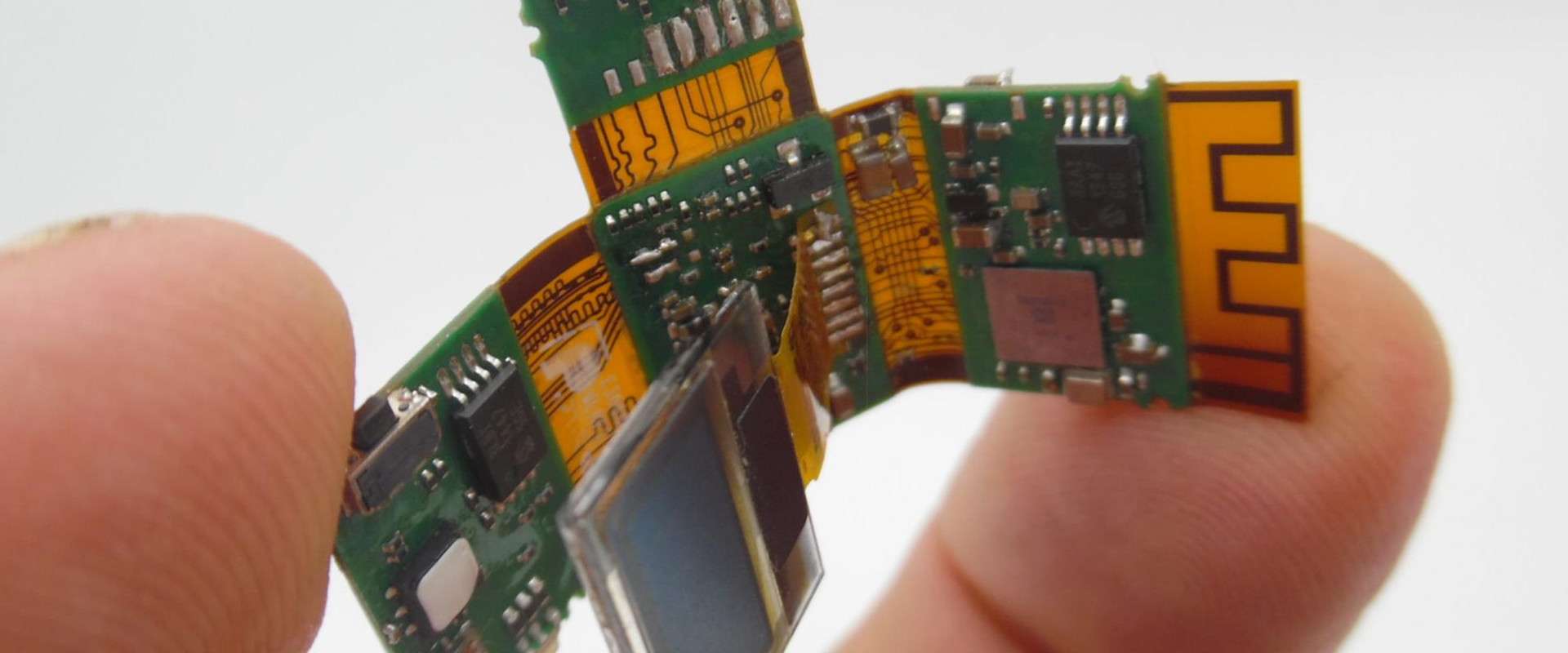
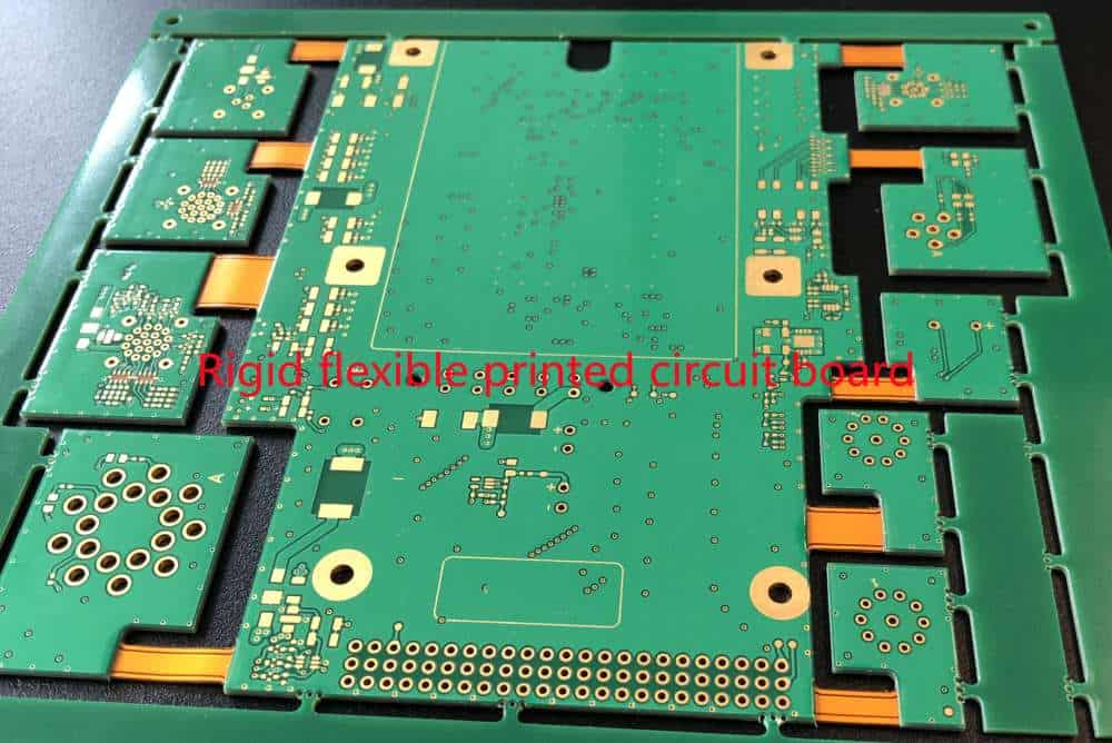
A rigid flex assembly is a type of printed circuit board that consists of rigid and flexible substrates laminated together into a single structure. The rigid sections provide mechanical support while the flexible sections allow dynamic flexing and movement. Rigid flex assemblies provide solutions for applications where flexibility, space savings, and reliability are critical requirements.
Rigid flex technology emerged in the 1960s for aerospace applications. Today it is widely used in various industries including medical, telecommunications, automotive, industrial, and consumer electronics. The global rigid flex circuit market was valued at $12.87 billion in 2020 and is projected to reach $18.73 billion by 2026.
Benefits of Rigid Flex Assemblies
Here are some of the key benefits offered by rigid flex assemblies:
- Space savings: Rigid flex takes up less space compared to traditional cabling or connectors between PCBs. The folds in the flex circuit allow 3D configuration of rigid sections.
- Flexibility: The flex sections provide dynamic flexing, vibration dampening, and improved reliability under mechanical stress. They can withstand millions of flex cycles.
- Weight reduction: Replacing discrete wires and cables with lightweight flex circuits reduces system weight. This is advantageous in aerospace, automotive and portable electronics applications.
- Reliability: Rigid flex circuits have fewer interconnects compared to using separate rigid PCBs and cables. This results in improved reliability and reduced failure points.
- Design freedom: Rigid flex allows greater freedom in placing components across multiple rigid areas connected by flex circuits. Components can be located based on electrical logic rather than mechanical constraints.
- Reduced assembly cost: Automated assembly methods like roll-to-roll processing enable efficient and cost-effective manufacturing of rigid flex circuits.
Applications of Rigid Flexible Circuits
Here are some common applications that benefit from using rigid flex assemblies:
- Aerospace: Flight control systems, engine controls, in-flight entertainment systems
- Medical: Endoscopes, hearing aids, surgical equipment
- Automotive: Drive-by-wire systems, anti-lock brakes, engine controls
- Telecom: Mobile phones, base stations, servers
- Defense: Guidance systems, radars, communications equipment
- Industrial: Robotics, instrumentation, control panels
- Consumer Electronics: Laptops, wearables, handheld scanners
Design Considerations for Rigid Flex
Designing a rigid flex assembly requires careful planning and engineering analysis. Here are some important considerations:
Layer Stackup
The rigid and flex sections can have different layer counts based on requirements. Typical rigid layer counts range from 2 to 30 layers or more. Flex layers are typically limited to 2-4 layers. The rigid layers provide thickness while the thinner flex allows dynamic bending.
Dielectric Materials
The rigid portions typically use standard FR-4 dielectric. The flexible sections use polyimide films like Kapton or UPILEX which can withstand repeated bending without damage. Adhesive layers bond the layers together.
Conductor Selection
Copper foils are universally used as conductors. Flex layers use rolled annealed copper foil. Rigid layers can use standard ED copper or rolled copper. Plated through holes (PTHs) provide connections between layers.
Stiffener and Coverlay
Stiffeners made from materials like aluminum or FR-4 are added to provide mechanical strength to the rigid regions. Coverlay protects the conductor traces on the external flex layers.
Bend Radius
The flex sections must be designed with an appropriate bend radius, minimum distance to first bend, and bend locations to avoid damage during movement.
Component Placement
Components are placed strategically across rigid portions to maximize design functionality within space and flexibility constraints.
Manufacturing Processes
Rigid flex PCBs require specialized fabrication. Here are some key manufacturing processes:
Layer Fabrication
The rigid and flexible layers are fabricated separately based on the required layer stackup. Rigid layers use standard PCB processes like imaging, etching, and lamination. Flex layers use lithography and etching on polyimide films.
Layer Alignment and Bonding
The fabricated layers are precisely aligned using optical registration systems. They are bonded together using adhesive films and heat and pressure in a lamination press.
Via Formation
PTHs and other vias are drilled and plated to form interconnections between layers as per the design. Flex-to-rigid interconnections require precise depth control.
Outer Layer Processing
Final finishes and coatings are applied to the outer layers. This includes solder mask, silkscreen, surface finishes like ENIG or immersion tin.
Component Assembly
Components are assembled on the rigid portions using SMT assembly lines. Additional alignment systems ensure accuracy during placement.
Functional Testing
Each completed assembly is tested for continuity, functionality according to circuit design, and dynamic flexure performance.
Key Rigid Flex Design Principles
Here are some important principles to follow when designing rigid flex assemblies:
- Minimize rigid layers in flex sections to maximize bendability
- Avoid placing plated through holes (PTHs) in bend areas
- Use teardrop PTH pads in flex areas to reduce stresses
- Place components in rigid areas, avoid component placement in flexing regions
- Design appropriate minimum bend radius for flex areas
- Allow sufficient distance between rigid sections for initial flex bend
- Plan layout and folds to maximize 3D packaging efficiency
- Analyze mechanical and thermal stresses for reliability
- Design rigid sections to provide structural stability
- Use design rules and constraints provided by manufacturer
- Prototype and test initial designs to verify performance
By following these principles, robust rigid flex circuits can be designed to meet application requirements.
Benefits of Using Rigid Flex Instead of Cables
Using rigid flex circuits instead of traditional cabling provides several advantages:
- Eliminates connectors between PCBs, increasing reliability
- Saves space compared to cables and connectors
- Provides dynamic flexing capability not possible with wires and cables
- Allows direct integration and bonding between PCBs
- Flex sections are immune to noise compared to parallel cables
- Rigid flex is lighter in weight than discrete wires
- Lower assembly time and cost due to fewer interconnects
- Flex traces can carry high speed signals with low cross-talk
- Enables greater design flexibility for component placement
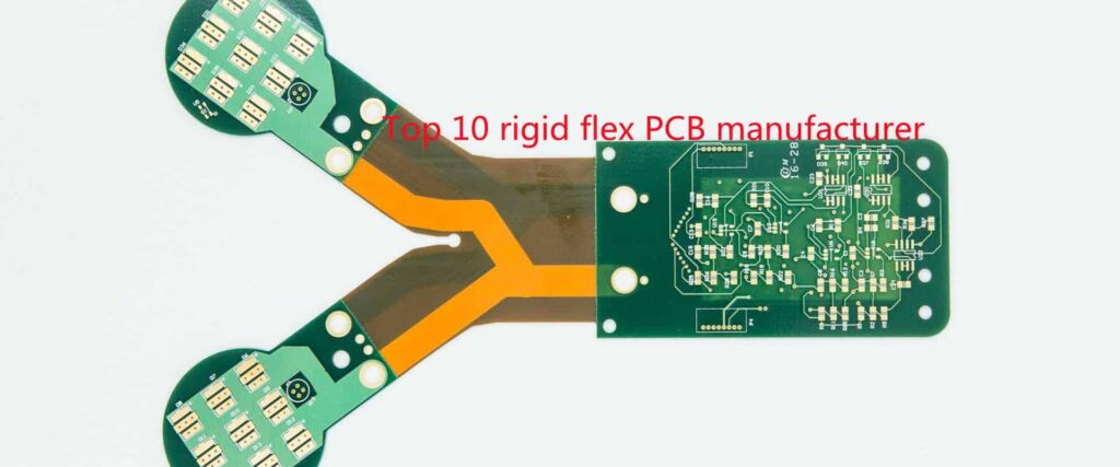
Selecting a Rigid Flex Manufacturer
Choosing the right rigid flex manufacturer is critical to get well-fabricated circuits that meet design and functional requirements. Here are important considerations:
- Experience with different types of rigid flex, including multilayer and HDI
- In-house engineering support for design review
- Capability to fabricate complex layer stackups and high layer counts
- Sophisticated processes for alignment, bonding, via formation
- Quality certifications such as ISO 9001 and AS 9100
- Competitive pricing and low minimum order quantities
- Supplier evaluation including quality/OTD metrics
- Geographical location, production capacity, and lead times
- Design support tools and verification testing
- Supply chain management and component sourcing
- Prototyping abilities and pre-production samples
- Effective customer service and program management
By selecting a capable rigid flex manufacturer, the overall development process can be streamlined.
FQA
What are some typical applications of rigid flex circuits?
Some typical applications that use rigid flex circuits are:
- Aerospace: Airplane control systems, engine controls, avionics
- Medical: Endoscopes, surgical handpieces, insulin pumps
- Automotive: Drive control systems, sensor assemblies
- Consumer Electronics: Mobile phones, laptops, cameras
- Industrial: Robotics, instrumentation, machine controls
What are some key benefits of rigid flex circuits?
Key benefits of rigid flex circuits include:
- Space savings from compact, integrated packaging
- Flexibility provided by the dynamic flex sections
- Improved reliability with fewer interconnects
- Lightweight compared to cables and wires
- Design freedom to position components optimally
- Efficient manufacturing and assembly
What are some critical design considerations for rigid flex?
Critical design considerations for rigid flex include:
- Bend radius for flex sections
- Distance between rigid areas for initial flex
- Layer stackup configuration and materials
- Component placement strategy
- Mechanical and thermal analysis
- High-precision alignment and bonding
- Testability and inspectability
What makes rigid flex manufacturing complex?
Rigid flex manufacturing is complex because:
- Separate fabrication processes for rigid and flex layers
- Precise optical alignment and bonding of layers
- Drilling/plating of small vias spanning rigid/flex areas
- Dealing with different materials and thicknesses
- Testing dynamic and static performance
- Achieving design complexity with small features
Why should cabling be avoided in favor of rigid flex?
Rigid flex should be used instead of cabling because:
- It saves space compared to bulky cables
- Provides flexibility unlike discrete wires
- Eliminates connectors between PCBs
- Is lighter weight than cables
- Has better signal performance than cables
- Enables direct bonding between PCBs
- Lowers assembly cost and time
- Improves overall system reliability
So in summary, rigid flex circuits provide technical and commercial benefits over traditional cabling approaches.


Leave a Reply