What is RGB Pinout?
RGB pinout refers to the arrangement and configuration of pins on a connector or interface that is used to control RGB (Red, Green, Blue) lighting or display devices. RGB is a color model that allows for the creation of a wide range of colors by combining different intensities of red, green, and blue light. RGB pinout is essential for proper communication and control between a controller or power source and the RGB device.
Common RGB Pinout Configurations
There are several common RGB pinout configurations used in various applications, such as LED strips, RGB displays, and computer peripherals. Here are some of the most widely used RGB pinout configurations:
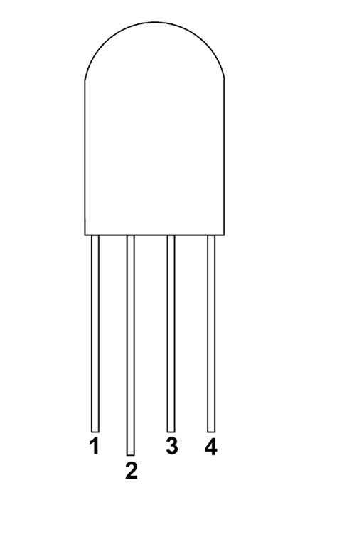
| Configuration | Pin 1 | Pin 2 | Pin 3 | Pin 4 |
|---|---|---|---|---|
| Common Anode | Red | Green | Blue | +V |
| Common Cathode | Red | Green | Blue | GND |
| RGB+W | Red | Green | Blue | White |
| RGBW | Red | Green | Blue | White |
-
Common Anode: In this configuration, the common pin is connected to the positive voltage (+V), and the red, green, and blue pins are connected to the respective LED cathodes. To control the color, the individual color pins are pulled low (connected to ground) to vary the intensity.
-
Common Cathode: In a common cathode configuration, the common pin is connected to ground (GND), and the red, green, and blue pins are connected to the respective LED anodes. To control the color, the individual color pins are pulled high (connected to a positive voltage) to vary the intensity.
-
RGB+W: This configuration includes an additional white LED along with the red, green, and blue LEDs. The white LED is controlled separately from the RGB LEDs, allowing for the creation of more diverse color combinations and white light.
-
RGBW: Similar to RGB+W, this configuration incorporates a white LED. However, in RGBW, the white LED is controlled in combination with the RGB LEDs, enabling more precise color mixing and a wider range of achievable colors.
RGB Pinout in LED Strips
LED strips are one of the most common applications of RGB lighting. They consist of a flexible circuit board with multiple RGB LEDs mounted along its length. Understanding the RGB pinout of LED strips is crucial for proper installation and control.
Types of LED Strips
There are two main types of LED strips based on their control method:
-
Analog LED Strips: Analog LED strips use a variable voltage signal to control the intensity of each color channel. They typically have three wires or pins corresponding to the red, green, and blue channels, along with a common power wire.
-
Digital LED Strips: Digital LED strips, also known as addressable LED strips, contain individually controllable RGB LEDs. Each LED on the strip has its own built-in controller, allowing for independent control of color and brightness. Digital LED strips often use protocols like WS2812B or SK6812 for communication.
Connecting LED Strips
When connecting LED strips, it’s essential to identify the correct RGB pinout and ensure proper power supply. Here are the general steps for connecting LED strips:
-
Identify the RGB Pinout: Determine the RGB pinout configuration of your LED strip. This information is usually provided in the product datasheet or printed on the strip itself.
-
Connect Power Supply: Connect the power wires (positive and ground) of the LED strip to a suitable power supply. Ensure that the power supply provides the required voltage and current rating for your LED strip.
-
Connect Control Wires: Connect the RGB control wires to the corresponding pins on your controller or microcontroller board. Make sure to match the pinout configuration (e.g., common anode or common cathode) between the LED strip and the controller.
-
Test and Verify: Once the connections are made, power on the system and test the functionality of the LED strip. Verify that the colors are displayed correctly and that the control signals are properly received.

RGB Pinout in Computer Peripherals
RGB lighting has become increasingly popular in computer peripherals, such as keyboards, mice, and fans. These devices often use RGB pinout to control the lighting effects and synchronize with software.
USB RGB Pinout
Many RGB peripherals use USB connectors for power and communication. The USB specification includes provisions for RGB lighting control. Here’s the typical USB RGB pinout:
| Pin | Function |
|---|---|
| 1 | +5V |
| 2 | Data – |
| 3 | Data + |
| 4 | Ground |
The RGB lighting control signals are usually sent over the data pins (D+ and D-) using protocols like USB HID (Human Interface Device) or proprietary vendor-specific protocols.
Motherboard RGB Pinout
Some computer motherboards include dedicated RGB headers for connecting RGB peripherals or LED strips. These headers provide a standardized pinout for easy compatibility. The most common motherboard RGB pinout is the 4-pin configuration:
| Pin | Function |
|---|---|
| 1 | +12V |
| 2 | G |
| 3 | R |
| 4 | B |
The 4-pin RGB header supplies 12V power and has individual pins for red, green, and blue color channels. Motherboard manufacturers may also include proprietary RGB headers with additional pins for extended functionality.

Controlling RGB Devices
To control RGB devices, you need a controller or a microcontroller that can generate the appropriate control signals. There are various methods and protocols used for RGB control, depending on the device and application.
PWM Control
Pulse Width Modulation (PWM) is a common technique used to control the intensity of RGB LEDs. PWM works by rapidly turning the LED on and off at a high frequency, with the duration of the “on” state (pulse width) determining the perceived brightness. By varying the pulse width for each color channel (red, green, blue), you can achieve different colors and intensities.
Addressable LED Control
Addressable LED strips, such as those using the WS2812B or SK6812 protocols, require a specific control signal to communicate with each individual LED. These protocols typically use a single data line to send serial data, which includes the color and brightness information for each LED. Microcontrollers with dedicated LED control libraries, such as FastLED or Adafruit NeoPixel, can be used to generate the necessary control signals.
Software Control
Many RGB peripherals come with software that allows for customization and control of the lighting effects. These software applications communicate with the device using the appropriate protocol (e.g., USB HID) and provide a user-friendly interface for selecting colors, patterns, and synchronization options. Some popular RGB control software include:
- Razer Synapse
- Corsair iCUE
- ASUS Aura Sync
- MSI Mystic Light

FAQs
-
What is the difference between common anode and common cathode RGB pinout?
In a common anode configuration, the common pin is connected to the positive voltage, and the individual color pins are pulled low to control the intensity. In a common cathode configuration, the common pin is connected to ground, and the individual color pins are pulled high to control the intensity. -
Can I connect an RGB LED strip directly to a USB port?
No, you cannot connect an RGB LED strip directly to a USB port. USB ports provide a limited amount of current, which is insufficient to power multiple RGB LEDs. You need a separate power supply that can provide the required voltage and current for your LED strip. -
How do I control RGB lighting on my computer peripherals?
RGB lighting on computer peripherals is typically controlled through software provided by the manufacturer. The software communicates with the device using protocols like USB HID and allows you to customize colors, patterns, and synchronization options. Refer to the manufacturer’s documentation for specific instructions on controlling RGB lighting on your peripherals. -
What is the purpose of the white LED in RGB+W and RGBW configurations?
The white LED in RGB+W and RGBW configurations serves two main purposes. First, it allows for the creation of pure white light without the need to mix red, green, and blue colors. Second, it enhances the overall color rendering and enables a wider range of achievable colors when combined with the RGB LEDs. -
Can I use any microcontroller to control addressable LED strips?
While most microcontrollers can be used to control addressable LED strips, some are better suited for the task than others. Microcontrollers with dedicated hardware peripherals for generating precise timing signals, such as the Arduino Uno or Teensy boards, are commonly used for controlling addressable LEDs. Additionally, using libraries like FastLED or Adafruit NeoPixel can simplify the programming process and provide a range of pre-built functions for LED control.
Conclusion
RGB pinout is a fundamental aspect of controlling RGB lighting and display devices. Understanding the different RGB pinout configurations, such as common anode, common cathode, RGB+W, and RGBW, is essential for proper installation and control. LED strips and computer peripherals are common applications of RGB lighting, each with their own specific pinout and control methods.
When working with RGB devices, it’s crucial to identify the correct pinout, ensure proper power supply, and use appropriate control techniques like PWM or addressable LED protocols. Microcontrollers and dedicated software can be used to generate control signals and customize lighting effects.
By familiarizing yourself with RGB pinout and control methods, you can effectively integrate RGB lighting into your projects and create visually appealing and dynamic displays. Whether you’re building an LED strip installation or customizing your computer peripherals, understanding RGB pinout is key to achieving the desired results.


Leave a Reply