What is a Relay Drive?
A relay drive, also known as a relay driver, is an electronic circuit that is used to control a relay, which is an electromechanical switch. The relay drive circuit takes a low-power input signal and converts it into a higher-power signal that can be used to energize the coil of the relay, causing the relay contacts to open or close.
Relays are commonly used in a wide range of applications, including automotive systems, industrial control systems, home automation, and more. They allow a low-power control signal to switch a much higher-power load, such as a motor, solenoid, or lighting circuit.
How Does a Relay Drive Work?
A relay consists of an electromagnet (coil) and a set of contacts. When current flows through the coil, it generates a magnetic field that attracts an armature, which in turn causes the relay contacts to switch from their normally open (NO) or normally closed (NC) position.
The role of the relay driver is to provide the necessary current to energize the relay coil when a control signal is received. The control signal is usually a low-power DC voltage, such as 5V or 12V from a microcontroller or other control circuit.
The basic components of a relay drive circuit include:
-
Input: This is the control signal that determines when the relay should be energized or de-energized. It could be a digital output from a microcontroller, a switch, or a sensor.
-
Relay driver: This is the main component of the circuit that takes the low-power input signal and converts it into a higher-power signal suitable for energizing the relay coil. It typically consists of a transistor or an integrated circuit (IC) specifically designed for driving relays.
-
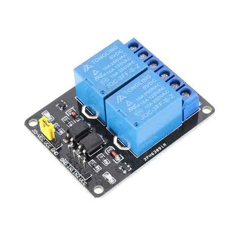
Relay: The electromechanical switch that is being controlled by the relay driver. It contains a coil and a set of contacts (NO, NC, or both).
-
Power supply: The source of power for the relay coil. It should provide the necessary voltage and current required by the relay.
-
Protection components: These include components such as diodes, resistors, and capacitors that help protect the relay driver and the control circuit from voltage spikes and other electrical noise generated by the switching of the relay.
When the input signal is applied to the relay driver, it switches on the transistor or IC, allowing current to flow through the relay coil. This current generates a magnetic field that causes the armature to move, switching the relay contacts. When the input signal is removed, the transistor or IC switches off, cutting off the current to the coil and allowing the armature to return to its original position, switching the contacts back to their default state.

Relay Drive Circuit Design Considerations
When designing a relay drive circuit, several factors need to be considered to ensure proper operation and reliability:
-
Relay coil voltage and current: The relay driver must be capable of supplying the necessary voltage and current to energize the relay coil. This information can be found in the relay’s datasheet.
-
Input signal characteristics: The relay driver must be compatible with the input control signal, such as its voltage level, polarity, and current sourcing or sinking capability.
-
Switching speed: If the application requires fast switching, the relay driver and the relay itself must be capable of operating at the desired speed.
-
Isolation: In some cases, electrical isolation may be required between the control circuit and the relay driver to protect the control circuit from high voltages or electrical noise.
-
Protection: Proper protection components, such as flyback diodes, should be included to suppress voltage spikes generated by the relay coil when it is de-energized.

Types of Relay Drivers
There are several types of relay drivers, each with its own advantages and limitations. Some common types include:
-
Transistor-based relay drivers: These use a single transistor (BJT or MOSFET) to switch the relay coil current. They are simple and inexpensive but may require additional components for protection and current amplification.
-
IC-based relay drivers: These are dedicated integrated circuits designed specifically for driving relays. They often include built-in protection features and can handle higher currents than transistor-based drivers. Examples include the ULN2003 and the MAX4427.
-
Optocoupler-based relay drivers: These use an optocoupler to provide electrical isolation between the control circuit and the relay driver. They are useful in applications where high voltages or electrical noise could damage the control circuit.
-
Solid-state relays (SSRs): While not a relay driver in the traditional sense, SSRs are a solid-state alternative to electromechanical relays. They use semiconductor devices to switch the load and offer faster switching speeds, longer lifetimes, and silent operation compared to mechanical relays.

Application Circuits
Relay drives are used in a wide variety of applications across many industries. Some common application circuits include:
1. Automotive relay control
In automotive systems, relays are used to control various high-power loads, such as headlights, horns, and starter motors. A typical automotive relay control circuit using a transistor-based relay driver is shown below:
[Insert schematic diagram of an automotive relay control circuit]
In this circuit, the microcontroller provides a low-power control signal to the base of the transistor, which in turn switches the relay coil current. The flyback diode (D1) protects the transistor from voltage spikes generated by the relay coil when it is de-energized.
2. Industrial control systems
Relays are extensively used in industrial control systems to control motors, solenoids, and other high-power loads. A typical industrial relay control circuit using an IC-based relay driver (ULN2003) is shown below:
[Insert schematic diagram of an industrial relay control circuit using ULN2003]
The ULN2003 is a high-voltage, high-current Darlington transistor array IC that can drive up to seven relays simultaneously. It includes built-in flyback diodes for relay coil protection and can be directly interfaced with microcontrollers or other control circuits.
3. Home automation
In home automation systems, relays are used to control lighting, appliances, and other electrical loads. A typical home automation relay control circuit using an optocoupler-based relay driver is shown below:
[Insert schematic diagram of a home automation relay control circuit using an optocoupler]
The optocoupler provides electrical isolation between the low-voltage control circuit (e.g., a microcontroller) and the high-voltage relay driver. This isolation protects the control circuit from damage due to high voltages or electrical noise. The transistor on the output side of the optocoupler switches the relay coil current.
Relay Drive Troubleshooting
When working with relay drive circuits, you may encounter various issues that prevent the relay from operating correctly. Some common problems and their solutions are listed below:
| Problem | Possible Causes | Solutions |
|---|---|---|
| Relay does not switch | 1. Insufficient coil voltage or current 2. Faulty relay 3. Incorrect wiring |
1. Ensure the power supply provides the correct voltage and current for the relay coil 2. Replace the relay 3. Check and correct the wiring |
| Relay switches intermittently | 1. Loose connections 2. Electrical noise interference |
1. Check and tighten all connections 2. Use shielded cables, add Bypass Capacitors, or use an optocoupler for isolation |
| Relay driver overheating | 1. Excessive current draw 2. Insufficient heat dissipation |
1. Use a relay driver with a higher current rating or use multiple drivers in parallel 2. Add a heat sink to the relay driver or improve ventilation |
| Relay contacts arcing or burning | 1. Switching high-inductive loads without protection 2. Switching high-current loads beyond relay contact rating |
1. Add a flyback diode or RC snubber across the relay contacts 2. Use a relay with higher contact ratings or use multiple relays in parallel |
Frequently Asked Questions (FAQ)
1. What is the difference between a relay and a relay driver?
A relay is an electromechanical switch that uses an electromagnet to control a set of contacts. A relay driver is an electronic circuit that provides the necessary current to energize the relay coil, allowing it to switch the contacts.
2. Can I use a transistor to drive a relay directly?
Yes, a transistor can be used to drive a relay directly. However, you must ensure that the transistor can handle the relay coil current and that appropriate protection components, such as a flyback diode, are included in the circuit.
3. How do I choose the right relay for my application?
When choosing a relay, consider factors such as the required voltage and current ratings for the coil and contacts, the switching speed, the number and type of contacts (NO, NC, or both), and the operating environment (temperature, humidity, etc.). Consult the relay manufacturer’s datasheet for detailed specifications.
4. Can I use a solid-state relay (SSR) instead of an electromechanical relay?
Yes, solid-state relays can be used in place of electromechanical relays in many applications. SSRs offer advantages such as faster switching speeds, longer lifetimes, and silent operation. However, they may have lower current and voltage ratings compared to electromechanical relays and may require heat sinks for proper heat dissipation.
5. How can I protect my relay drive circuit from voltage spikes and electrical noise?
To protect your relay drive circuit from voltage spikes and electrical noise, you can use various protection components such as:
1. Flyback diodes: Connected across the relay coil to suppress voltage spikes generated when the coil is de-energized.
2. RC snubbers: Connected across the relay contacts to suppress arcing and extend contact life.
3. Optocouplers: Provide electrical isolation between the control circuit and the relay driver, protecting the control circuit from high voltages and noise.
4. Bypass capacitors: Connected across the power supply to filter out high-frequency noise.
By understanding the working principles, design considerations, and application circuits of relay drives, you can effectively control high-power loads using low-power control signals in a wide range of applications. Proper component selection, circuit design, and protection measures are essential to ensure the reliable and efficient operation of relay drive circuits.


Leave a Reply