Introduction
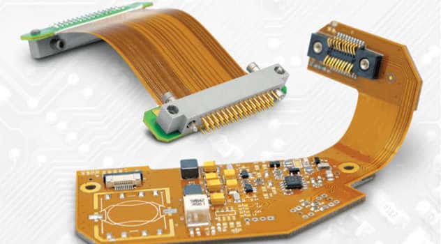
Polyimide flex circuits, also known as flexible printed circuits (FPCs), are made using the polymer polyimide as the base substrate material. Polyimide is prized for its thermal stability, chemical resistance, and mechanical toughness. These properties make polyimide ideal for flex circuit applications where flexibility, durability, and reliability are critical.
Flex circuits enable three-dimensional wiring and interconnections for electronic devices and components. They provide many advantages over traditional rigid printed circuit boards (PCBs) including:
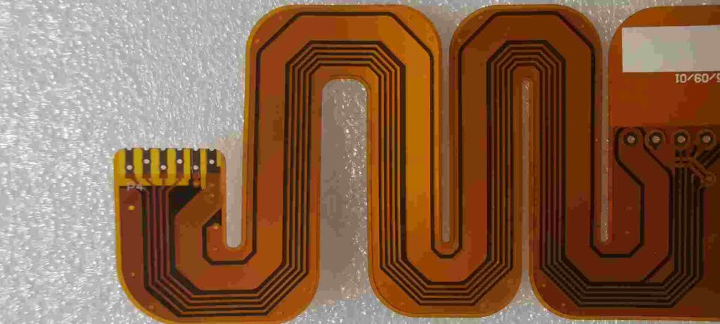
- Flexibility – can be bent and folded repeatedly without damage
- Lightweight – thinner and lower mass than rigid boards
- Space savings – can fit into tight spaces and move dynamically
- Reliability – excellent flex life and fatigue resistance
- Design freedom – can take any shape to optimize layout and space
Polyimide flex circuits are ubiquitous today, found in consumer electronics, automotive, medical, aerospace, and industrial applications. This article provides an in-depth look at polyimide flex circuit design, manufacturing processes, and applications.
Polyimide Flex Circuit Design
The design of a polyimide flex circuit starts with understanding the application requirements and constraints. Key design considerations include:
Circuit Layout
- Component placement – optimal layout for routing and 3D shape
- Trace widths/spacings – match impedance and current needs
- Copper thickness – balance flexibility with current loads
- Stiffeners – reinforce high stress or connection areas
- Vias – enable vertical interconnections as needed
Substrate Properties
- Polyimide thickness – balances flexibility with handling and reliability
- Coverlay thickness – protects traces from wear and environmental damage
- Adhesive type – maintains flexibility and adhesion reliability
Mechanical Factors
- Dynamic flexing – account for repeated bending cycles
- Static shape – match shape to usage contours
- Mounting – method for securing flex circuit
- Strain relief – prevent tearing at connections
Electrical Performance
- Impedance control – match trace geometries to maintain impedance
- Crosstalk – space traces and planes to minimize interference
- Shielding – contain EMI/RFI using ground planes or shields
- Signal integrity – ensure clean signals throughout flex
The designer must synthesize all these parameters to create a flex circuit optimized for the particular application. Simulation, prototyping, and testing help verify the design.
Polyimide Flex Circuit Materials
Polyimide flex circuits have three key material components:
Polyimide Substrate
The polyimide base gives the circuit its flexible properties. Key attributes:
- High heat resistance – glass transition >300°C
- Chemically inert – resistant to most solvents and acids
- Dimensionally stable – low Z-axis expansion
- Tough and cut-resistant – withstands abrasion
- Excellent dielectric properties
Polyimide films commonly used include DuPont Kapton, Ube Upilex, and Kaneka Apical. The polyimide thickness typically ranges from 25 to 125 microns.
Copper Conductors
Flex circuit traces and pads are formed from rolled annealed copper foil, usually 12 to 35 microns thick. Copper provides excellent conductivity and ductility. A thin nickel/gold plating is usually added to prevent oxidation and improve solderability.
Coverlay
The coverlay is a flexible dielectric layer laminated over the copper traces to provide protection from wear, abrasion, and environmental damage. Polyimide is most often used as coverlay to match the base material. The coverlay has openings for connections and component pads.
Polyimide Flex Circuit Fabrication
Producing a polyimide flex circuit involves several specialized fabrication processes:
Lamination
Polyimide sheets and copper foils are laminated together using adhesives that cure at elevated temperatures. This bonds the materials into a stable flexible substrate for photolithographic processing.
Photolithography
Using photoresist and lithographic exposure, the desired circuit trace pattern is transferred to the copper layer. Etching then removes the unwanted copper, leaving only the traces and pads.
Coverlay Lamination
The patterned flex circuit has coverlay applied over the traces for protection. Laser ablation forms openings in the coverlay at solder pads and testpoints.
Plating
Exposed copper is plated with nickel and immersion gold to inhibit oxidation and enable soldering. Electroless nickel provides even coverage.
Testing
100% electrical testing checks for shorts and opens. Automated optical inspection looks for defects. Impedance testing verifies matched transmission lines.
Singulation
Flex circuits are cut from panels into individual circuits using lasers or steel rule dies. Precise alignments maintain trace tolerances.
Polyimide Flex Circuit Applications
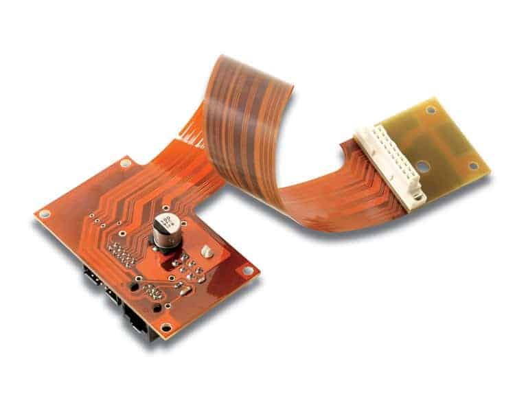
Polyimide flex circuits are found across many industries due to their unique combination of flexibility, reliability, and durability.
Consumer Electronics
Compact folding in smartphones, wearables, game controllers, and VR headsets. Dynamic contours in displays.
Automotive
Engine control units, transmission sensors, crossing multiple hinge points. High temperatures in engine bays.
Medical
Implantable devices, hearing aids, catheter-based electronics. Biocompatible, moisture resistant.
Industrial
Robotics, factory automation, machine controls. Withstands vibration, contamination, moisture.
Aerospace and Military
Guidance systems, avionics, satellite mechanisms. Stable dielectric properties in space.
As electronic devices continue getting smaller and more portable, flexible circuits will become increasingly critical for interconnectivity and dynamic mechanical capabilities. Polyimide is likely to remain the material of choice thanks to its outstanding thermal, chemical, and mechanical characteristics. Continued advances in polyimide technology and flex circuit fabrication will open up new application spaces and design possibilities.
Frequently Asked Questions
What are some key benefits of using polyimide instead of PVC or PET for flex circuits?
Polyimide offers superior thermal properties, chemical resistance, and mechanical toughness compared to PVC (polyvinyl chloride) and PET (polyethylene terephthalate). Polyimide has much higher heat resistance, allowing use in high temperature applications up to 300°C. It also maintains its properties and dimensions better than PVC or PET. Polyimide has excellent chemical resistance and won’t be damaged by exposure to most solvents. It is also physically very durable and resistant to cuts and abrasion damage from repeated flexing. These characteristics make polyimide the preferred choice for demanding flex circuit applications.
What are some best practices for dynamic flexing of polyimide flex circuits?
- Avoid excessive sharp bending. Maintain bend radius greater than 6X circuit thickness.
- Secure circuit to prevent unintended bending or vibration.
- Provide strain relief where external cables connect.
- Qualify flex life with repeated cycling under application conditions.
- Seal circuits to prevent moisture ingress at flex points.
- Ensure complete adhesive cure to maximize flex properties.
- Utilize compliant lead-free solders to allow flexing.
- Strategically place flexures along the circuit.
- Analyze stresses using FEA modeling. Reinforce high stress junctions.
How are components assembled onto polyimide flex circuits?
Surface mount technology is most commonly used. Solder paste is screened onto pads, components placed, then soldered by reflow oven. For plated through-hole parts, solder is applied by wave soldering or selective hand soldering. Automated pick-and-place assembly can place both SMT and PTH parts. Polyimide coverlay provides solder mask for controlled solder application. Adhesives may supplement solder with components in high vibration/shock areas. Careful process control is needed for reliable assembly on thin, flexible circuits.
How well does polyimide bond to different metallization layers like copper and gold?
Polyimide forms a high strength chemical linkage with metals like copper and gold through coordination bonding between the metal atoms and the polyimide functional groups. This produces superior adhesion compared to just van der Waals forces. Polyimide-to-copper bond strength typically exceeds 5 lb/in width, which exceeds the cohesive strength within the bulk copper. With proper surface preparation, polyimide-to-metal adhesion reliability is extremely robust and suitable for the most demanding flex circuit applications.
What are important considerations when designing controlled impedance transmission lines on flex circuits?
- Use impedance calculators to determine trace width/space for target impedance
- Minimize thickness variations in polyimide and copper
- Ensure consistent dielectric properties through proper curing
- Watch for impedance variations when flexed – strategic stiffeners or specific materials may help
- Model effects of various bend radii on impedance
- Utilize ground/reference planes to increase stability
- Test impedance using TDR or other electrical test methods
- Optimize board layout to minimize abrupt impedance changes
- Match trace geometries to connectors and other components


Leave a Reply