Introduction
Printed Circuit Boards (PCBs) are the backbone of modern electronics. They are used in almost every electronic device, from smartphones and laptops to medical equipment and aerospace systems. PCBs are designed to connect electronic components and provide a stable platform for them to function properly. However, even a small defect in a PCB can lead to system failure, which can be costly and dangerous. This is where PCB Testing comes in.
PCB testing is a critical process that ensures the quality and reliability of PCBs before they are used in electronic devices. There are several testing methods that can be used to detect defects and ensure that PCBs meet the required specifications. In this article, we will discuss the eight most common PCB testing methods that you need to know.
Why is PCB Testing Important?
PCB testing is essential for several reasons:
-
Quality Assurance: PCB testing ensures that the manufactured PCBs meet the required quality standards and specifications. It helps identify defects early in the manufacturing process, reducing the risk of defective products reaching the market.
-
Cost Savings: Detecting defects early in the manufacturing process can save a lot of money. It is much cheaper to fix a defect during the manufacturing stage than to recall a product from the market due to a defective PCB.
-
Safety: PCBs are used in critical applications such as medical devices and aerospace systems. A defective PCB can lead to system failure, which can be dangerous and even life-threatening. PCB testing ensures that the PCBs used in these applications are reliable and safe.
-
Regulatory Compliance: Many industries have strict regulations and standards that electronic products must meet. PCB testing helps ensure that the PCBs used in these products comply with the relevant regulations and standards.

The 8 PCB Testing Methods You Need To Know
1. Visual Inspection
Visual inspection is the most basic and common PCB testing method. It involves visually examining the PCB for any obvious defects such as scratches, cracks, or contamination. This method can also detect issues such as incorrect component placement, solder bridges, or missing components.
Visual inspection can be done manually or using automated optical inspection (AOI) systems. AOI systems use cameras and image processing software to detect defects that may be missed by the human eye.
2. Automated Optical Inspection (AOI)
Automated optical inspection (AOI) is a more advanced version of visual inspection. It uses cameras and image processing software to detect defects on the PCB surface. AOI systems can detect a wide range of defects, including:
- Solder defects (e.g., bridging, insufficient solder, excess solder)
- Component defects (e.g., missing, misaligned, or incorrect components)
- PCB defects (e.g., scratches, contamination, or damage)
AOI systems can inspect PCBs at high speeds and with high accuracy. They can also generate reports and data for quality control and traceability purposes.
3. X-Ray Inspection
X-ray inspection is a non-destructive testing method that uses X-rays to detect defects inside the PCB. This method is particularly useful for detecting defects in multi-layer PCBs or in areas that are not visible to the naked eye.
X-ray inspection can detect defects such as:
- Voids in solder joints
- Broken or missing wire bonds
- Cracks or delamination in the PCB substrate
- Misaligned or missing components
X-ray inspection can be done using 2D or 3D X-ray systems. 3D X-ray systems provide a more detailed view of the PCB and can detect defects that may be missed by 2D systems.
4. In-Circuit Testing (ICT)
In-circuit testing (ICT) is a method that tests the functionality of individual components on the PCB. It involves using a bed-of-nails fixture to make electrical contact with the PCB and test each component separately.
ICT can detect defects such as:
- Open or short circuits
- Incorrect component values
- Missing or incorrect components
- Damaged or defective components
ICT is a fast and reliable testing method, but it requires a custom fixture for each PCB design. This can be costly and time-consuming for low-volume production or prototype testing.
5. Flying Probe Testing
Flying probe testing is an alternative to ICT that does not require a custom fixture. Instead, it uses a set of movable probes to make electrical contact with the PCB and test each component separately.
Flying probe testing can detect the same defects as ICT, but it is slower and less accurate. However, it is more flexible and can be used for low-volume production or prototype testing.
6. Boundary Scan Testing
Boundary scan testing is a method that tests the interconnections between components on the PCB. It involves adding boundary scan cells to each component on the PCB and using a boundary sCAN Controller to test the connections between them.
Boundary scan testing can detect defects such as:
- Open or short circuits between components
- Stuck-at faults (i.e., a signal that is stuck at a high or low level)
- Delay faults (i.e., a signal that takes too long to propagate)
Boundary scan testing is particularly useful for testing complex PCBs with high-density interconnects. It can also be used for programming and debugging embedded systems.
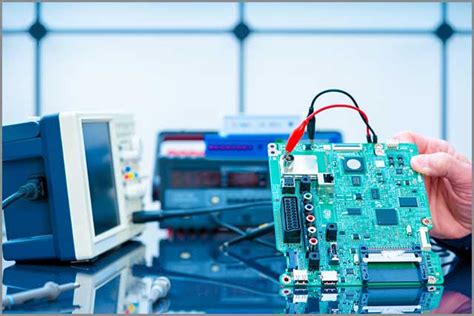
7. Functional Testing
Functional testing is a method that tests the overall functionality of the PCB. It involves connecting the PCB to a test system and running a series of tests to verify that it performs as expected.
Functional testing can detect defects such as:
- Incorrect or missing functionality
- Compatibility issues with other components or systems
- Performance issues (e.g., speed, power consumption, or signal integrity)
Functional testing is typically done at the end of the manufacturing process to ensure that the PCB is ready for use in the final product.
8. Environmental Testing
Environmental testing is a method that tests the PCB’s ability to withstand various environmental conditions. It involves exposing the PCB to extreme temperatures, humidity, vibration, or other environmental stresses to ensure that it can operate reliably in the intended environment.
Environmental testing can detect defects such as:
- Cracking or delamination of the PCB substrate
- Failure of components or solder joints due to thermal stress
- Corrosion or degradation of materials due to humidity or other environmental factors
Environmental testing is particularly important for PCBs that will be used in harsh environments such as aerospace, automotive, or industrial applications.

PCB Testing Methods Comparison
| Testing Method | Defects Detected | Speed | Accuracy | Cost | Flexibility |
|---|---|---|---|---|---|
| Visual Inspection | Obvious defects (e.g., scratches, cracks, contamination) | Fast | Low | Low | High |
| Automated Optical Inspection (AOI) | Solder defects, component defects, PCB defects | Fast | High | Medium | Medium |
| X-Ray Inspection | Internal defects (e.g., voids, cracks, misaligned components) | Medium | High | High | Medium |
| In-Circuit Testing (ICT) | Open/short circuits, incorrect component values, missing/incorrect components | Fast | High | High | Low |
| Flying Probe Testing | Open/short circuits, incorrect component values, missing/incorrect components | Slow | Medium | Medium | High |
| Boundary Scan Testing | Interconnect defects, stuck-at faults, delay faults | Fast | High | Medium | Medium |
| Functional Testing | Incorrect/missing functionality, compatibility issues, performance issues | Medium | High | Medium | High |
| Environmental Testing | Environmental stress-related defects (e.g., cracking, corrosion) | Slow | High | High | Low |

FAQ
1. What is the most common PCB testing method?
The most common PCB testing method is visual inspection. It is the simplest and fastest method and can detect obvious defects such as scratches, cracks, or contamination.
2. What is the most accurate PCB testing method?
The most accurate PCB testing methods are automated optical inspection (AOI), X-ray inspection, and boundary scan testing. These methods can detect defects with high accuracy and reliability.
3. What is the most cost-effective PCB testing method?
The most cost-effective PCB testing method depends on the specific requirements of the PCB and the production volume. For low-volume production or prototype testing, flying probe testing may be the most cost-effective option. For high-volume production, automated optical inspection (AOI) or in-circuit testing (ICT) may be more cost-effective.
4. What is the fastest PCB testing method?
The fastest PCB testing methods are visual inspection, automated optical inspection (AOI), and boundary scan testing. These methods can inspect PCBs at high speeds and with high accuracy.
5. What PCB testing methods are required for safety-critical applications?
For safety-critical applications such as medical devices or aerospace systems, multiple PCB testing methods may be required to ensure the highest level of reliability and safety. These may include visual inspection, automated optical inspection (AOI), X-ray inspection, in-circuit testing (ICT), boundary scan testing, functional testing, and environmental testing.
Conclusion
PCB testing is a critical process that ensures the quality, reliability, and safety of PCBs used in electronic devices. There are several PCB testing methods available, each with its own advantages and limitations. The choice of testing method depends on the specific requirements of the PCB, the production volume, and the intended application.
Visual inspection and automated optical inspection (AOI) are the most common PCB testing methods and can detect a wide range of defects. X-ray inspection and boundary scan testing are useful for detecting internal defects and interconnect issues. In-circuit testing (ICT) and flying probe testing are used for testing individual components, while functional testing and environmental testing ensure that the PCB performs as expected in the intended environment.
By understanding the different PCB testing methods and their applications, manufacturers can ensure that their PCBs meet the highest quality and reliability standards. This can help reduce costs, improve safety, and enhance customer satisfaction in the highly competitive electronics industry.


Leave a Reply