Introduction to Flex Circuits and Rigid-Flex
Printed circuit boards (PCBs) provide the foundation for almost all modern electronics. Traditional PCBs use rigid laminated sheets made of materials like FR-4 glass epoxy. However, many applications require circuits that can bend and flex. Flexible printed circuits (FPCs) and rigid-flex PCBs provide solutions when deformation is required.
What are Flex Circuits?
A flexible PCB, or flex circuit, is made of flexible dielectric materials like polyimide or polyester. Thin layers of copper trace out the circuit patterns, allowing the board to bend and fold without damage. Components mount to designated stiffened areas on the flex PCB.
Flexible circuits can dynamically flex and bend. This makes them useful for applications where:
- Motion is required – such as Robotics, wearables, Medical devices
- Space is constrained – Consumer electronics, aerospace, and military products
- Durability is critical – Automotive, industrial, and commercial uses
Common flex circuit applications include computer displays, mobile devices, control panels, and medical electronics.
What are Rigid-Flex PCBs?
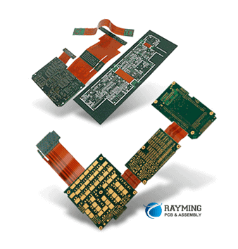
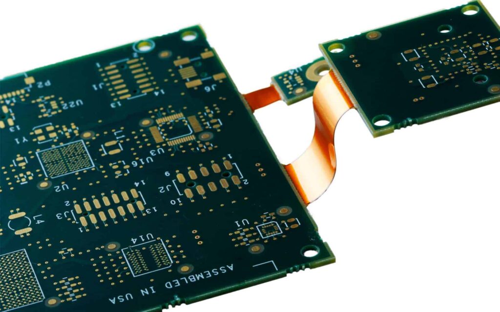
Rigid-flex PCBs provide the best of both worlds – rigid board sections integrate with flexible circuits. They contain both rigid laminate materials (like FR-4) and flexible dielectric films.
Rigid areas provide:
- Stiffness for component mounting
- Protection and reduced wear on flexible materials
- Easy integration with other PCBs
Flexible areas enable:
- Dynamic folding and shaping
- 3-dimensional configuration
- Moving joints and hinges
Incorporating both types of materials lets rigid-flex boards fit into tight spaces. They also withstand vibration, bending, and frequent flexing. Common rigid-flex applications include cameras, robots, IoT devices, and medical electronics.
Benefits of Flexible and Rigid-Flex PCBs
Choosing flex circuits or rigid-flex boards provides a range of advantages over traditional rigid PCBs:
Dynamic Movement and Positioning
The flexible sections of the PCB can bend, twist, and fold to move dynamically. This enables custom configurations, movements, and compact packing of electronics.
Adaptability and Shape
Flex circuits and rigid-flex PCBs can adapt to almost any shape or form factor. They can snake around components or curve around corners.
Soft Interconnections
Flexible circuits provide soft, malleable interconnections between multiple rigid PCBs or components. This removes the need for connector cables.
Space and Weight Savings
By eliminating connectors and cables, flex and rigid-flex PCBs save space and reduce weight. This makes them perfect for dense, compact devices.
Improved Reliability
Continuous circuits mean fewer soldered connections. This improves reliability and reduces failures.
Design Freedom
Combining rigid and flex materials provides more design freedom. Rigid-flex enables creative innovations not possible with one-piece rigid boards.
Reduced Assembly Costs
Consolidating interconnections onto flex circuits reduces production costs. Automated assembly lowers fabrication expenses.
Rigid-Flex Design and Material Considerations
Successfully designing and manufacturing rigid-flex PCBAs requires understanding the materials and processes involved. Here are some important design considerations.
Layer Stacking
A rigid-flex board will contain both rigid and flexible layer stacks. The designer must strategically use materials suited for each section. Stacks may include layers like:
- Rigid layers: FR-4, polyimide
- Flex layers: Polyimide, polyester
- Bonding films: Acrylic or epoxy adhesives
Dielectric Materials
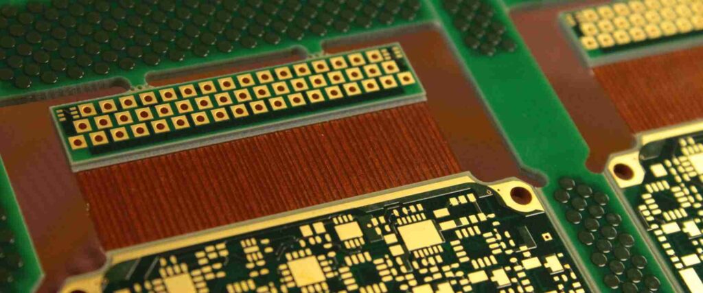
Common flexible dielectric films include polyimide (Kapton) and polyester (PET). Polyimide provides thermal stability at high temps, while polyester offers flexibility and bending endurance. Thinner materials provide more flexibility.
Conductor Traces
Copper foil forms the conductive traces in flexible circuits. Very thin foils down to 12 microns support tight bend radiuses. Special flex adhesives bond the foil.
Cover layers
Protective cover layers shield external conductor traces from wear and environmental damage. Polyimide and acrylic coatings are common choices.
Bend Radius
Track routing and stackup must account for minimum bend radius rules. Inside bends see compression, outside bends see tension. Tight radii increase risk of conductor cracking.
Layer Transitions
Moving between rigid and flex sections requires special processing. Filled castellations provide smooth transitions between material types.
Stiffening Elements
Strategically placed stiffeners, ribs, and supports reinforce the flex circuit. This prevents unwanted bending while allowing movement and folding along defined fold lines.
Designing Rigid-Flex PCBs
Designing a reliable rigid-flex board requires advanced PCB layout skills. Here is an overview of critical design considerations:
Layer Stack Planning
- Define all required rigid and flexible layers
- Select suitable dielectric materials
- Plan layer transitions between rigid and flex areas
Circuit Protection
- Use flexible, elastic solders to reduce cracking
- Implement fail-safe circuits with redundant traces
- Remove sharp copper edges
Trace Routing
- Use broad traces for high-current power circuits
- Route traces along the board neutral axis when possible
- Avoid acute-angle traces
Bend Areas
- Plan fold lines and hinge points early
- Ensure no components lie in bending areas
- Account for tear propagation dangers
Mounting Regions
- Add stiffening elements to strengthen component areas
- Use openings, slots and cutouts to reduce stiffness
Connectors and Terminals
- Reinforce solder joints
- Prevent failures by avoiding interfaces between rigid and flex
Rigid-Flex PCB Assembly and Manufacturing
Producing rigid-flex boards requires advanced manufacturing and assembly processes. Here is an overview:
Photolithography
High-precision photolithography patterns the copper layers onto the dielectric films. This typically uses automatic optical inspection (AOI).
Laser Direct Imaging
Laser direct imaging (LDI) can pattern flex and rigid layers simultaneously. It aligns layers with precision down to 25 microns.
Layer Alignment
Fiducials and targets support precise alignments between layers during lamination. X-ray inspection can verify alignment.
Automated Assembly
Pick-and-place assembly robots accurately populate components onto the reinforced mounting pads.
Soldering
Reflow soldering attaches components to the board. Special solders flexibly absorb stresses.
Protective Coatings
Additional layers like solder mask, silkscreen, and conformal coating help protect the finished board.
Testing
Electrical, continuity, and functional testing ensures boards operate to specifications before shipping.
Applications of Flexible and Rigid-Flex PCBs
Here are some common product applications that use flexible or rigid-flex PCBs:
Wearable Electronics
Fitness trackers, smart watches, headsets, and medical monitoring devices are compact wearables that require flexible circuits to move with the body comfortably.
Consumer Electronics
Phones, tablets, displays, cameras, and other consumer technology use flex circuits for interconnections as well as dynamic positioning.
Automotive Electronics
With rigorous demands, automotive apps like sensors, controls, and in-vehicle entertainment rely on durable, reliable flex circuit boards.
Industrial Electronics
Industrial controls, robotics, test and measurement devices, and other commercial electronics often require flexible and rigid-flex PCBs.
Medical Electronics
Medical devices like patient monitors, implants, and diagnostic equipment need adaptable, biocompatible flex and rigid-flex PCB solutions.
Military and Aerospace
Rigorous environments demand rugged, reliable rigid-flex boards for guidance systems, communications, navigation, and other uses.
Prototyping and Sourcing Rigid-Flex PCBs
Developing products with flex and rigid-flex PCBs requires finding a capable manufacturing partner. Here are key considerations:
- Work with the supplier during design to ensure manufacturability
- Request flex and rigid-flex prototyping to test design concepts
- Evaluate capabilities in high-density interconnects (HDI)
- Look for experience with challenging component assembly
- Discuss options like protective coatings and enclosures
- Review quality assurance and testing capabilities
- Determine suitable flexible materials based on requirements
- Confirm production capacity matches expected order volumes
- Make sure the supplier can provide the services you need (PCBA, design)
Choosing an established, experienced supplier gives access to specialized skills, customization services, and advanced rigid-flex manufacturing processes. They support innovators in delivering highly reliable, well-designed flex and rigid PCB solutions.
Frequently Asked Questions
What are some pros and cons of rigid-flex PCBs?
Pros:
- Dynamic flexing, bending, folding
- Adaptable to custom shapes
- Integrates multiple rigid and flex layers
- Eliminates connectors and cables
- Saves weight and space
- Withstands vibration and frequent flexing
- Enables innovation in product design
Cons:
- More expensive than rigid boards
- Challenging to design and manufacture
- Requires special assembly and soldering
- Needs careful trace routing for flex areas
- Limitations on component types and placements
How do costs compare between rigid and rigid-flex PCBs?
Rigid-flex PCBs typically cost more than rigid boards. Reasons include:
- Specialized materials like polyimide flex dielectrics
- Additional processing steps
- Precise layer-to-layer registration
- Advanced manufacturing techniques
- Lower panel utilization during fabrication
- More complex assembly and component mounting
However, rigid-flex PCBs can reduce total system cost through space, connector, and cable savings.
What are some guidelines for trace routing on rigid-flex PCBs?
- Use smooth curves instead of acute angles
- Avoid traces perpendicular to bend axis
- Route critical signals on inner layers
- Keep traces broad and thin
- Plan redundant traces on separate layers
- Leave extra space for rigid-flex transitions
- Allow extra trace lengths for flexing
- Minimize length differences between same net traces
How do you prevent failures at a rigid-to-flex transition?
Rigid-to-flex interfaces require careful design and processing. Recommendations include:
- Use filled castellations for smooth layer transitions
- Implement cured bonding films between rigid and flex
- Avoid placing components directly on transitions
- Reinforce solder joints near transitions
- Redirect traces away from transitions
- Improve reliability with redundant parallel traces
- Prevent tear propagation with stiffeners and slit designs
What are important considerations for components mounted on rigid-flex PCBs?
- Select compact, lightweight components
- Consider moisture sensitivity levels (MSL)
- Prefer flat top component geometries
- Use flexible solder joints
- Stiffen areas under components
- Avoid placing on fold lines or transitions
- Reduce mechanical stress on solder joints
- Account for different CTE between components and flex PCB
How can you test and inspect flexible PCBs?
Testing approaches for flex PCBs include:
- Visual inspection of materials, topology, trace routing
- Automated optical inspection (AOI) for defects
- X-ray imaging to verify layer alignment
- Flying probe electrical testing
- Bed-of-nails fixture circuit testing
- Continuity checks for opens/shorts
- Functional testing while flexing the board
- Environmental stress testing – bending, vibration, temperature, humidity
- Post-assembly inspection and device testing
Conclusion
Flexible printed circuits and rigid-flex PCBs enable innovative electronics in challenging applications like wearables, mobile devices, automotive, aerospace, and medical products. Combining the properties of both rigid and flexible materials supports compact design with dynamic movement and resilience. With careful layout and component mounting, rigid-flex boards reliably adapt to the most demanding electrical and mechanical requirements. Leveraging the benefits of flex and rigid-flex PCB technology allows designers to keep pushing the boundaries of possibility.


Leave a Reply