Table of Contents
- Introduction to PCB Connectors
- Common PCB Connector Types
- Board-to-Board Connectors
- Wire-to-Board Connectors
- Cable-to-Board Connectors
- Power Connectors
- RF Connectors
- Factors to Consider When Choosing PCB Connectors
- Pitch and Density
- Current Rating
- Mating Cycles
- Operating Temperature
- Environmental Considerations
- PCB Connector Materials and Plating
- PCB Connector Mounting Types
- Best Practices for PCB Connector Selection and Design
- Frequently Asked Questions (FAQ)
- Conclusion
Introduction to PCB Connectors
PCB connectors play a vital role in establishing electrical and mechanical connections between printed circuit boards and various components, devices, or subsystems. They facilitate the transfer of power, signals, and data, enabling seamless communication and functionality within electronic systems.
The choice of PCB connector type depends on several factors, including the application requirements, signal characteristics, power demands, space constraints, and environmental conditions. Understanding the different connector types and their properties is essential for making informed decisions during the design and assembly process.

Common PCB Connector Types
Board-to-Board Connectors
Board-to-board connectors are used to establish connections between two printed circuit boards. They provide a reliable and compact solution for interconnecting PCBs in various configurations, such as stacking, edge-to-edge, or mezzanine arrangements. Some common board-to-board connector types include:
- Mezzanine Connectors: These connectors allow vertical stacking of PCBs, often used in high-density applications where space is limited.
- Card Edge Connectors: These connectors utilize the exposed copper fingers on the edge of a PCB to mate with a corresponding socket, commonly found in expansion cards and modules.
- Board-to-FPC Connectors: These connectors are designed to connect flexible printed circuits (FPCs) to rigid PCBs, offering a low-profile and space-saving solution.
| Connector Type | Pitch | Current Rating | Mating Cycles |
|---|---|---|---|
| Mezzanine | 0.5mm – 1.27mm | Up to 5A per pin | 50 – 500 |
| Card Edge | 1.27mm – 2.54mm | Up to 3A per pin | 50 – 200 |
| Board-to-FPC | 0.3mm – 1.0mm | Up to 1A per pin | 10 – 50 |
Wire-to-Board Connectors
Wire-to-board connectors are used to establish connections between individual wires or wire harnesses and PCBs. They provide a means to interface external devices, sensors, or power sources with the PCB. Some popular wire-to-board connector types include:
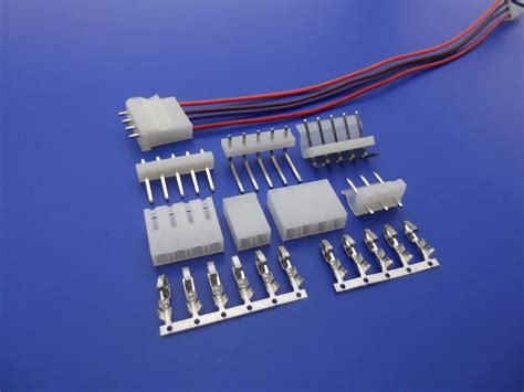
- Crimp Connectors: These connectors utilize crimp terminals that are crimped onto the wires and then inserted into a housing that mates with the PCB.
- Screw Terminal Connectors: These connectors feature screw terminals that allow wires to be securely fastened to the PCB using screws.
- IDC (Insulation Displacement Connectors): These connectors have sharp contacts that pierce the insulation of the wires, establishing a connection without the need for stripping or crimping.
| Connector Type | Pitch | Current Rating | Mating Cycles |
|---|---|---|---|
| Crimp | 1.25mm – 5.08mm | Up to 10A per contact | 20 – 100 |
| Screw Terminal | 2.54mm – 10.16mm | Up to 30A per contact | 50 – 200 |
| IDC | 1.27mm – 2.54mm | Up to 3A per contact | 10 – 50 |
Cable-to-Board Connectors
Cable-to-board connectors are designed to interface cables with PCBs, allowing for the transfer of signals, power, or data between the board and external devices or systems. Some commonly used cable-to-board connector types include:
- USB Connectors: These connectors are widely used for connecting USB devices to PCBs, supporting various USB standards such as USB 2.0, USB 3.0, and USB Type-C.
- HDMI Connectors: These connectors are used for transmitting high-definition video and audio signals between PCBs and displays or multimedia devices.
- Ethernet Connectors: These connectors, such as RJ45, are used for connecting PCBs to Ethernet networks, enabling high-speed data communication.
| Connector Type | Data Rate | Current Rating | Mating Cycles |
|---|---|---|---|
| USB 2.0 | Up to 480 Mbps | Up to 1.5A | 1,500 |
| USB 3.0 | Up to 5 Gbps | Up to 1.5A | 1,500 |
| HDMI | Up to 18 Gbps | Up to 0.5A | 10,000 |
| Ethernet (RJ45) | Up to 10 Gbps | Up to 1.5A | 750 |
Power Connectors
Power connectors are specialized connectors used for delivering power to PCBs from external power sources or between different sections of a PCB. Some common power connector types include:
- Barrel Connectors: These connectors have a cylindrical shape and are commonly used for low-voltage DC power supply connections.
- Molex Connectors: These connectors are widely used for power distribution in various applications, offering a range of sizes and current ratings.
- ATX Power Connectors: These connectors are used in computer power supplies to provide power to motherboards and other components.
| Connector Type | Voltage Range | Current Rating | Mating Cycles |
|---|---|---|---|
| Barrel | Up to 48V DC | Up to 5A | 5,000 |
| Molex | Up to 600V | Up to 30A | 50 – 100 |
| ATX | 12V, 5V, 3.3V | Up to 20A per pin | 50 – 100 |
RF Connectors
RF (radio frequency) connectors are used for connecting high-frequency signals between PCBs and antennas, coaxial cables, or other RF devices. Some popular RF connector types include:
- SMA Connectors: These connectors are commonly used for microwave frequencies up to 18 GHz and offer good mechanical stability.
- BNC Connectors: These connectors are used for RF signals up to 4 GHz and are often found in video and instrumentation applications.
- U.FL Connectors: These connectors are miniature surface-mount connectors used for high-frequency signals in space-constrained applications.
| Connector Type | Frequency Range | Impedance | Mating Cycles |
|---|---|---|---|
| SMA | Up to 18 GHz | 50 Ω | 500 – 1,000 |
| BNC | Up to 4 GHz | 50 Ω or 75 Ω | 500 – 1,000 |
| U.FL | Up to 6 GHz | 50 Ω | 30 – 50 |

Factors to Consider When Choosing PCB Connectors
When selecting PCB connectors for your design, several key factors should be considered to ensure optimal performance and reliability:
Pitch and Density
The pitch refers to the distance between the centers of adjacent pins or contacts in a connector. A smaller pitch allows for higher density and more compact designs, while a larger pitch provides better mechanical stability and ease of manufacturing. Consider the space constraints and signal requirements of your application when choosing the appropriate pitch.
Current Rating
The current rating specifies the maximum amount of current that a connector can safely carry per pin or contact. Ensure that the selected connector has a current rating sufficient to handle the power requirements of your application, considering factors such as voltage drop and temperature rise.
Mating Cycles
Mating cycles refer to the number of times a connector can be mated and unmated before its performance degrades. Consider the expected number of mating cycles in your application and choose a connector with a rating that exceeds your requirements. Connectors with higher mating cycles are generally more durable and reliable.
Operating Temperature
The operating temperature range of a connector specifies the minimum and maximum temperatures at which it can function reliably. Ensure that the selected connector can withstand the expected temperature range in your application, considering factors such as ambient temperature, self-heating, and thermal cycling.
Environmental Considerations
Consider the environmental conditions in which your PCB will operate, such as humidity, vibration, shock, and chemical exposure. Choose connectors with appropriate ratings and protections, such as sealing, plating, or ruggedized designs, to ensure reliable performance in harsh environments.

PCB Connector Materials and Plating
The materials and plating used in PCB connectors play a crucial role in their performance, durability, and reliability. Common materials used for connector housings include:
- Plastic: Lightweight, cost-effective, and suitable for general-purpose applications.
- Metal: Offers better mechanical strength, shielding, and thermal conductivity for demanding environments.
- Ceramic: Provides excellent insulation, high-temperature stability, and resistance to corrosion.
The contact plating used in PCB connectors affects their electrical conductivity, corrosion resistance, and durability. Some common plating options include:
- Gold: Offers excellent corrosion resistance, conductivity, and durability, but is relatively expensive.
- Tin: Provides good solderability and conductivity at a lower cost, but may be prone to oxidation over time.
- Nickel: Offers good corrosion resistance and durability, often used as an underplating for gold or tin.
Choose the material and plating combinations that best suit your application’s requirements, considering factors such as cost, performance, and environmental conditions.
PCB Connector Mounting Types
PCB connectors can be mounted on the board using various methods, depending on the design requirements and manufacturing processes. The most common mounting types include:
- Through-Hole Mounting: The connector pins are inserted through holes drilled in the PCB and soldered on the opposite side. This method provides strong mechanical stability but requires more board space.
- Surface-Mount Technology (SMT): The connector is mounted directly on the surface of the PCB using solder pads. SMT connectors offer higher density, smaller footprints, and compatibility with automated assembly processes.
- Press-Fit Mounting: The connector pins are forcefully inserted into plated through-holes on the PCB, establishing a mechanical and electrical connection without soldering. This method allows for easy assembly and disassembly.
Consider the available board space, manufacturing capabilities, and assembly requirements when selecting the appropriate mounting type for your PCB connectors.
Best Practices for PCB Connector Selection and Design
To ensure optimal performance and reliability of your PCB connectors, follow these best practices during the selection and design process:
- Understand the Application Requirements: Clearly define the electrical, mechanical, and environmental requirements of your application to guide your connector selection.
- Consider Signal Integrity: Choose connectors with appropriate signal integrity characteristics, such as impedance matching, shielding, and crosstalk reduction, especially for high-speed or sensitive signals.
- Design for Manufacturing: Select connectors that are compatible with your manufacturing processes and assembly methods, considering factors such as footprint, solderability, and automation.
- Provide Adequate Clearance: Ensure sufficient clearance around the connectors for mating and unmating, as well as for any required assembly or maintenance tasks.
- Follow Manufacturer Guidelines: Adhere to the manufacturer’s recommendations for connector handling, soldering, and assembly to ensure optimal performance and reliability.
- Perform Thorough Testing: Conduct comprehensive testing and validation of your PCB connectors, including mechanical, electrical, and environmental tests, to ensure they meet the desired specifications and reliability requirements.
By following these best practices and carefully considering the various factors discussed in this article, you can make informed decisions when selecting and designing PCB connectors for your applications.
Frequently Asked Questions (FAQ)
-
Q: What is the difference between through-hole and surface-mount PCB connectors?
A: Through-hole connectors have pins that are inserted through holes in the PCB and soldered on the opposite side, providing strong mechanical stability but requiring more board space. Surface-mount connectors are mounted directly on the surface of the PCB using solder pads, offering higher density and smaller footprints. -
Q: How do I choose the appropriate current rating for my PCB connector?
A: The current rating of a connector should be chosen based on the maximum expected current flow through each pin or contact in your application. Consider factors such as voltage drop, temperature rise, and safety margins when selecting the appropriate current rating. -
Q: What is the significance of mating cycles in PCB connectors?
A: Mating cycles refer to the number of times a connector can be mated and unmated before its performance degrades. Connectors with higher mating cycles are more durable and reliable, especially in applications where frequent connect/disconnect operations are expected. -
Q: What are the advantages of using gold-plated contacts in PCB connectors?
A: Gold-plated contacts offer excellent corrosion resistance, electrical conductivity, and durability compared to other plating options. They are often used in high-reliability applications or environments with harsh conditions. However, gold plating is relatively expensive compared to alternatives like tin or nickel. -
Q: How can I ensure signal integrity when using PCB connectors for high-speed signals?
A: To maintain signal integrity in high-speed applications, choose connectors with appropriate characteristics such as matched impedance, shielding, and crosstalk reduction. Follow proper design guidelines for signal routing, grounding, and termination, and consider using differential signaling or high-performance connector designs when necessary.
Conclusion
PCB connectors play a vital role in establishing reliable and efficient connections between printed circuit boards and various components, devices, or systems. Understanding the different connector types, their characteristics, and the factors to consider when selecting them is essential for designing robust and high-performance electronic systems.
By familiarizing yourself with the common PCB connector types, such as board-to-board, wire-to-board, cable-to-board, power, and RF connectors, you can make informed decisions based on your application requirements. Consider factors like pitch, current rating, mating cycles, operating temperature, and environmental conditions to ensure optimal performance and reliability.
Additionally, pay attention to the materials, plating, and mounting types of PCB connectors, as they impact durability, conductivity, and compatibility with manufacturing processes. Follow best practices for connector selection and design, including understanding application requirements, considering signal integrity, designing for manufacturing, providing adequate clearance, adhering to manufacturer guidelines, and performing thorough testing.
By staying informed about the latest developments and trends in PCB connector technology and applying the knowledge gained from this comprehensive guide, you can effectively navigate the world of PCB connectors in 2023 and beyond, enabling you to design and develop cutting-edge electronic products with confidence.


Leave a Reply