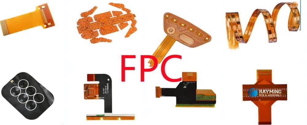
What is a PCB Board Stiffener?
A printed circuit board (PCB) stiffener is a rigid plate or frame that is attached to a PCB to reinforce it and prevent warping or flexing. Stiffeners help minimize stresses and maintain the flatness of the PCB during assembly, shipping, and use.
PCB stiffeners are especially useful for large boards, thin boards, boards with heavy components on one side, or boards that will be subject to vibration, shock, or frequent assembly/disassembly. Without an adequate stiffener, these types of PCBs can warp or bow during processing and in the field, potentially causing failure.
Why Use a PCB Stiffener?
There are several key benefits to using a PCB stiffener:
- Prevents warping/bowing: The stiffener resists deformation forces and keeps the PCB flat. This ensures proper fit during assembly and operation.
- Provides mechanical support: The stiffener reinforces weak areas and prevents cracking/breakage. This is important for thin, large, or flexible PCBs.
- Aids component alignment: A stiffener minimizes movement so components stay in alignment during processing and use.
- Improves connectivity: By preventing warping, stiffeners maintain proper contact between the PCB, components, and connectors.
- Enables effective heat sinking: A stiffener promotes flatness for maximum contact with heat sinks or cold plates.
- Reduces vibration/shock damage: The stiffener dampens vibrations and strengthens the board against shocks.
Stiffener Materials and Design
PCB stiffeners can be made from various materials, with aluminum and steel being most common. Other options include rigid plastics, carbon fiber composites, and plexiglass.
The optimal material depends on factors like:
- Cost
- Weight
- Strength
- Thermal conductivity
- Electrical conductivity
- Compatibility with PCB fabrication and assembly processes
Aluminum provides high strength at low weight along with excellent thermal conductivity. Steel offers very high strength and rigidity. Plastics and composites provide electrical insulation when needed.
Stiffener Thickness
The thickness of the stiffener material impacts its rigidity. Thicker stiffeners are stronger but also heavier. For most applications, aluminum stiffeners range from 0.8mm to 6mm thickness. Steel stiffeners are typically 0.8mm to 3mm thick.
The required thickness depends on:
- PCB size
- Component weight distribution
- Dynamic loads (vibration, shock)
- Stiffener span length
A general guideline is to make the stiffener thickness equal to or greater than the thickness of the PCB itself.
Stiffener Design
Common stiffener designs include:
- Solid plates: A single plate of material that covers a portion or the entire PCB surface area. Simple and inexpensive but provides limited access to board.
- Interlocking end plates: Plates at each end of the PCB connected by bridges or ribs in between. Allows some component access.
- Picture frames: A rectangular frame around the PCB perimeter. Maximizes access but provides less strength than solid plates.
- Cut-outs and holes: Openings in the stiffener reduce weight while maintaining strength. Allows access as needed.
- Ribs and bosses: Localized stiffening features for focused support. Used to strengthen specific areas without adding full plates.
The optimal design strikes a balance between strength, weight, cost, and accessibility. It depends on the specific PCB layout and component placement.
Stiffener Analysis and Simulation
To ensure an effective stiffener design, engineers should perform analysis and simulation including:
- Finite element analysis (FEA): Predicts stresses and deformation in the PCB with and without the stiffener. Validates strength and rigidity.
- Thermal simulation: Models heat flow through PCB and stiffener. Checks for hot spots and temperature gradients.
- Vibration analysis: Simulates dynamic vibration loads. Verifies stiffener natural frequencies are compatible with application.
- Shock testing: Subjects PCB and stiffener to simulated shock pulses. Confirms robustness against drops and impacts.
- Warpage analysis: Calculates predicted warpage/bowing of unstiffened PCB. Informs minimum stiffener requirements.
Analysis and simulation help optimize the stiffener design upfront before physical prototyping. They identify potential problems early when changes are easier.
Example FEA of PCB Stiffener
Here is an example finite element analysis of a PCB and aluminum stiffener plate:
FEA model of PCB with aluminum stiffener plate.
The FEA predicts how the PCB substrate will deform under vacuum pressure applied during soldering:
FEA results showing PCB warpage without stiffener (left) and minimized warpage with stiffener (right).
This analysis validates the stiffener design and thickness prior to prototyping. It prevents costly design iterations.
Stiffener Implementation Guidelines
Proper implementation of the stiffener is critical for achieving the desired performance benefits:
Stiffener Flatness
The stiffener itself should have minimal bow or twist. Excessive deviation from flatness will transfer to the PCB. Aluminum tooling plate is ideal for maintaining flatness.
Stiffener Attachment
Securely attaching the stiffener to the PCB is crucial. Typical methods include:
- Adhesives (epoxy, silicone)
- Mechanical fasteners (screws, rivets)
- Soldering
- Press-fit pins
- Clips/springs
Adhesives provide the best shock/vibration resistance while fasteners give the highest rigidity.
Minimize Gaps
Gaps between the stiffener and PCB allow flexibility and warping. Use shims or adhesives to fill any significant gaps.
Thermal Decoupling
With metals like aluminum or steel, insulate the stiffener from thermally sensitive areas of the PCB using Kapton tape, thermal pads, or other insulators.
Electrical Isolation
If the stiffener contacts circuits, use insulation to prevent electrical shorts. Anodized aluminum provides built-in insulation.
Proper stiffener integration ensures maximum strengthening benefit. Work closely with your PCB assembly vendor for optimal implementation.
Example PCB Stiffener Applications
Some examples where PCB stiffeners are commonly used:
Power Electronics
Large PCBs with heavy heat sinks, bus bars, and other components often require stiffening to avoid warpage and cracking.
High-Speed Digital
Thin, multilayer boards with high component density need reinforcement to withstand handling and vibration.
RF/Microwave
Stiffeners keep RF PCBs rigid for consistent electrical performance and robust connectivity.
Automotive
PCBs in vehicle systems are subjected to vibration, shock, and temperature swings. Stiffeners protect against failures.
Aerospace
Aircraft PCBs experience intense vibration along with shock landing loads. Stiffeners are essential for reliability.
Medical
Portable ultrasound, imaging, and diagnostic devices contain large, thin PCBs that require support.
In general, any large, thin, densely populated, or dynamically loaded PCB is a good candidate for stiffening.
PCB Stiffener Design Process
Here is a general workflow for implementing PCB stiffeners successfully:
- Evaluate PCB design considerations: Size, layer count, components, thermal loads, dynamic conditions.
- Perform initial stiffener design: Material, thickness, plate locations, cutouts, etc.
- Conduct FEA and other simulations to optimize the design.
- Review PCB layout and coordinate stiffener placement with component positions.
- Finalize stiffener design based on feedback from PCB designer.
- Fabricate prototype PCB with stiffener. Test for warpage, vibration, thermal issues.
- Iterate on design if needed to address any problems observed in prototyping.
- Finalize stiffener implementation details with PCB assembly vendor.
- Complete manufacturing with optimized, validated stiffener design.
Involving the PCB designer early and iterating based on prototyping results ensures a successful stiffener implementation.
Frequently Asked Questions
What is the typical cost to add a PCB stiffener?
The cost depends on the stiffener size and material. A basic aluminum plate stiffener can range from $50 to $500. More complex machined or custom designs are up to $1000 or more.
When should I use adhesive vs. mechanical fasteners to attach a stiffener?
Adhesives provide the best vibration resistance. Fasteners give higher strength and removability. A combination works well. Use fasteners for initial assembly then adhesive at pressure points.
How are stiffeners designed for flexible PCBs?
With flex PCBs, segmented stiffeners allow bending while still providing strengthening where needed. Epoxy adhesives work better than rigid mechanical attachments.
Can PCB stiffeners be installed by the end user?
User installation of stiffeners is not recommended as it risks damage to the PCB. Stiffeners are best attached by trained assembly technicians at the factory.
How can I analyze stiffener effectiveness for my PCB design?
FEA simulation is recommended to model stiffener performance. PCB stress, warpage, vibration response, thermal gradients, and shock loads can be estimated.
This covers the key considerations for using PCB stiffeners. Proper design and integration of stiffeners can significantly improve the reliability and lifespan of printed circuit boards in demanding applications. With upfront analysis and prototyping, stiffeners can be optimized to keep PCBs robust under all required operating conditions.


Leave a Reply