The printed circuit board (PCB) is the backbone of electronics. It provides the foundation on which components are mounted and connected to create an electronic circuit. A key property of PCBs is their flexural rigidity or stiffness. The ability of a PCB to flex to a degree without breaking is referred to as “PC board flex”. It is an important consideration in PCB design and manufacturing. In this comprehensive guide, we will cover all the key aspects of PC board flex and discuss its significance in electronics.
What is PC Board Flex?
PC board flex refers to the amount a printed circuit board can bend or flex without damage. It is measured by the flexural rigidity or stiffness of the board. The flexural rigidity depends on:
- Board thickness
- Materials used in layers
- Layer stackup
- Reinforcements
PCBs with high flexural rigidity do not bend easily, while flexible PCBs can bend significantly without damage. Flexible PCBs have very low flexural rigidity.
The amount of acceptable flex depends on the application. For example, rigid PCBs in computers may not flex at all in use. But PCBs in wearable devices need to handle repeated flexing. Knowing the right amount of flex needed is vital in PCB design.
Why is PC Board Flex Important?
Understanding PC board flex is critical for the following reasons:
1. Avoiding Mechanical Damage
If a PCB has inadequate flexural rigidity for an application, it may bend excessively and break traces or joints. Cracks can also develop over time with repeated flexing. Mechanical damage due to excessive flex is a reliability risk.
2. Preventing PCB Warpage
Too much flex during manufacturing can cause warpage of the PCB. This leads to assembly issues and rework costs. Controlling board flex ensures flat PCBs.
3. Accommodating Product Enclosure Design
The PCB stiffness affects the structural stability of the product enclosure. PC board flex must match the amount of bend needed to fit the board into the enclosure.
4. Enabling Flexible Circuits
Flexible PCBs by design have very low flexural rigidity. Controlling the flexural properties allows developing circuits that can bend repeatedly. Flex-to-install PCBs are an example.
5. Managing Dynamic Flexing
In dynamic applications, the PCB experiences continuous flexing. Understanding the fatigue life with repeated flex cycles is critical in such uses.
6. Preventing Stress on Components
Components mounted on the board undergo stress as the board flexes. Excessive component stress can cause solder joint or internal damage. Managing PCB stiffness prevents this.
7. Thermal Management
A PCB’s ability to flex allows conforming to surfaces and improves heat dissipation in some cases. Controlled flexural rigidity enables exploiting this benefit.
In summary, considering PC board flex is vital to reliability, manufacturing yield, enclosure design, flexible circuits, fatigue life, component stress, and thermal management.
How to Measure PC Board Flexibility
The flexibility or stiffness of a PCB is quantified by its flexural rigidity. This represents the resistance offered by the board against bending. The main methods used to measure PC board flex are:
Three-Point Bend Testing
This involves bending the test board over two points by applying force at a third point. The flexural rigidity is calculated from the applied force and the deflection produced.
Four-Point Bend Testing
Here, the board is bent over two points by applying forces at two more points. This allows testing a section of the board avoiding edge effects.
Vibration Testing
The PCB is subjected to vibrational excitation spanning a range of frequencies. Resonant frequencies indicate the board’s propensity to flex.
Laser Vibrometry
A laser beam reflected off the PCB measures vibration amplitude and mode shapes. This reveals resonances and flexing behavior.
Strain Gauges
Strain gauges attached to the board measure strain while flexing. This gives an indication of flexural rigidity.
Finite Element Analysis
FEA software is used to simulate flexural behavior using the material properties and PCB stackup. This predicts flexural rigidity.
Each test method has pros and cons. The preferred approach depends on factors like required accuracy, cost, time, facilities available, and tester expertise.
How to Improve PC Board Flexibility
The flexural rigidity of a PCB can be optimized by design techniques like:
- Using high Tg flexible materials as substrate dielectric
- Keeping board and copper thickness to a minimum
- Optimizing layer stackup configuration
- Using buried capacitance dielectric material
- Adding distributed or localized flex cuts
- Using intermittent copper patterns and hinging
- Adding slits or voids in the board layers
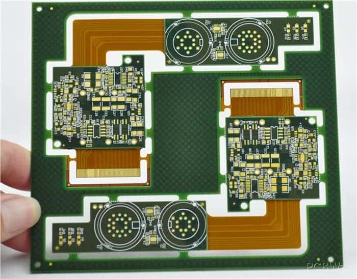
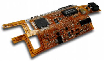
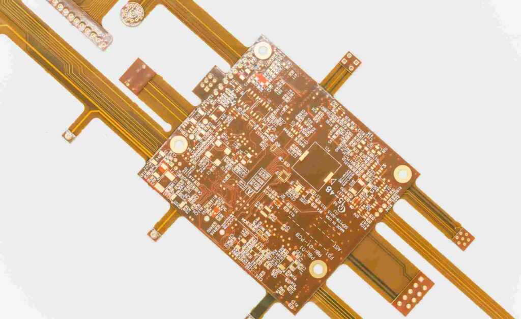
- Using rigid-flex or flex-rigid designs
- Allowing small air gaps in packaging around flex areas
- Conformal coating for improved fatigue life
Here are some examples of design optimization approaches:<table> <caption>Examples of Flexibility Improvement Methods</caption> <tr> <th>Method</th> <th>Description </th> </tr> <tr> <td>Flex Cuts</td> <td>Small cuts through all layers relieve stress and improve flex tolerance</td> </tr> <tr> <td>Intermittent Copper</td> <td>Copper patterns are segmented in the flex area keeping continuity</td> </tr> <tr> <td>Buried Capacitance Dielectric</td> <td>Materials like aramid or polyimide provide high bendability </td> </tr> <tr> <td>Rigid-Flex Design</td> <td>Combines rigid sections with flexible sections on the same board</td> </tr> </table>
Effects of Flexing on PCB Components
Components mounted on a flexible PCB will experience mechanical stress as the board flexes. The main effects are:
- Solder joint fatigue: Repeated flexing applies stress to solder joints. This can cause cracks and intermittent contacts.
- Leads flexing: Component leads and terminations flex along with the board. This can break the leads.
- Pad liftoff: Pads can delaminate from the board substrate when flexed excessively.
- Cracked bodies: Ceramic chip components may crack due to board flexing.
- Popcorning: Moisture absorption and rapid heating can make components crack and bulge out due to flexing stresses.
- Damage of rigid components: Large, heavy or rigid components may get damaged by board flexing.
Proper component selection, mounting arrangements, and adhesives are needed to mitigate these effects. Components ideal for flexible boards include:
- Small surface mount components
- Compliant leads (e.g. J-lead)
- Flexible or elastic substrates
- Chip-scale packages (CSP)
- Flat no-lead packages
- Small outline packages (SOIC, SOP)
- Plastic leaded chip carriers (PLCC)
Key Considerations in Flexible PCB Design
To design a flexible PCB successfully, engineers need to consider:
- Service flex requirements: Required bend radius, repeat cycles, dynamic or static flexing
- Mechanical stability: Preventing damage from vibration, shock, torque, etc.
- Component selection and layout: Choosing suitable components and minimizing rigid sections
- Reliability testing: Validating flex life through bend cycling, drop testing
- Manufacturing factors: Fabrication process limitations on flex severity, handling considerations
- Enclosure integration: Ensuring adequate flex clearance in product housing
- Reinforcement: Adding thickness locally by soldermask buildup to reduce flexing
- Flex patterning: Hinging techniques, controlling bend directions through board shaping
- ESD protection: Providing discharge paths on flexible circuits
- Thermal dissipation: Using thermal adhesives or gap pads for better heat transfer
Properly accounting for these aspects ensures a flexible PCB design that meets the application demands.
Common Applications of Flexible PCBs
The ability to bend repeatedly without damage makes flexible PCBs ideal for many applications such as:
- Wearable devices (smartwatches, fitness bands, health monitoring)
- Portable consumer electronics
- Medical equipment
- Industrial automation and robotics
- Aerospace and defense systems
- Automotive electronics
- Internet of Things (IoT) edge nodes
Flexible circuits allow innovative packaging, ease of assembly, reduced wiring, and improved reliability through controlled flex designed for the application environment.
Some examples of flexible PCB implementations are:
- Wearable device flex interconnects between rigid PCBAs
- Flex cabling for motion control in robotics
- Flex assembly attaching rigid boards in auto electronics
- Hinge flex circuits in foldable smartphones, laptops
- Helical/conical wraps in hearing aids
FQA
What is the most common way to test PC board flex?
The three-point bend test is the most common and cost-effective method used to characterize PCB flexural rigidity. It provides reasonably accurate measurement of flex performance under controlled lab conditions.
How does thickness affect PCB flexibility?
Thinner boards naturally allow more flex compared to thicker boards, given the same materials. Hence using the minimum required thickness is an effective way to improve flex capability.
Do all layers in a multilayer board affect flex equally?
No, the outer layers (copper + dielectric) have the maximum effect since they are furthest from the neutral axis. The sequence of stackup also influences flexural rigidity.
Can soldermask relief help in flexible PCBs?
Yes, soldermask relief on the board surface reduces points of stress concentration. This improves reliability under dynamic flexing conditions.
Are flexible PCBs tested for a minimum bend radius?
Yes, flexible PCB suppliers qualify boards to ensure they can withstand a minimum bend radius without damage. This is essential information for designers.


Leave a Reply