Introduction to the NRF24L01 Module
The NRF24L01 is a single-chip 2.4 GHz transceiver developed by Nordic Semiconductor. It is designed for ultra-low power wireless applications and can operate in the 2.4 GHz ISM band. The module features a built-in RF transceiver, baseband protocol engine, and Enhanced ShockBurst™ protocol, which provides automatic packet handling and reliable data transmission.
Key Features of the NRF24L01
- 2.4 GHz ISM band operation
- Data rate up to 2 Mbps
- Ultra-low power consumption
- Enhanced ShockBurst™ protocol for automatic packet handling
- 125 available RF channels
- Built-in antenna or external antenna support
- SPI interface for communication with microcontrollers
NRF24L01 Pinout and Pin Description
The NRF24L01 module comes in a small 20-pin QFN package. Here is a detailed description of each pin and its function:
| Pin Number | Pin Name | Description |
|---|---|---|
| 1 | GND | Ground |
| 2 | VCC | Supply voltage (1.9V to 3.6V) |
| 3 | CE | Chip Enable (active high) |
| 4 | CSN | Chip Select (active low) |
| 5 | SCK | SPI Clock |
| 6 | MOSI | SPI Slave Data Input |
| 7 | MISO | SPI Slave Data Output |
| 8 | IRQ | Interrupt (active low) |
| 9-14 | – | Not Connected |
| 15 | ANT1 | Antenna 1 |
| 16 | ANT2 | Antenna 2 |
| 17-20 | – | Not Connected |
Detailed Pin Descriptions
- GND: This pin is connected to the ground of the system.
- VCC: This pin is used to supply power to the module. The operating voltage range is 1.9V to 3.6V.
- CE (Chip Enable): This pin is used to enable or disable the module. When CE is high, the module is in active mode and can transmit or receive data.
- CSN (Chip Select): This pin is used to select the module for SPI communication. When CSN is low, the module is selected, and SPI communication can take place.
- SCK (SPI Clock): This pin is used to provide the clock signal for SPI communication.
- MOSI (SPI Slave Data Input): This pin is used to send data from the microcontroller to the NRF24L01 module.
- MISO (SPI Slave Data Output): This pin is used to send data from the NRF24L01 module to the microcontroller.
- IRQ (Interrupt): This pin is used to generate an interrupt signal when a specific event occurs, such as data received or transmitted successfully.
- ANT1: This pin is connected to the built-in antenna or can be used to connect an external antenna.
- ANT2: This pin is used when connecting an external antenna. It should be left unconnected when using the built-in antenna.

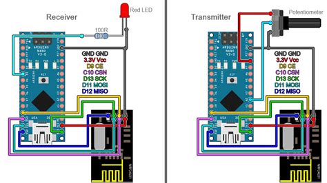
Connecting the NRF24L01 to a Microcontroller
To use the NRF24L01 module with a microcontroller, you need to establish an SPI connection between the two devices. Here’s a typical connection diagram:
| NRF24L01 Pin | Microcontroller Pin |
|---|---|
| VCC | 3.3V |
| GND | GND |
| CE | GPIO |
| CSN | GPIO |
| SCK | SPI SCK |
| MOSI | SPI MOSI |
| MISO | SPI MISO |
| IRQ | GPIO (optional) |
Make sure to connect the VCC pin to a 3.3V power supply, as the NRF24L01 is not 5V tolerant. Also, ensure that the microcontroller’s SPI pins are correctly configured and that the CE and CSN pins are set as outputs.

Configuring the NRF24L01
Before using the NRF24L01 module, you need to configure its various settings, such as the RF channel, data rate, and address. This is done by writing to specific registers using SPI commands.
Important Registers
- CONFIG: This register is used to configure the module’s operational mode, power-up delay, and CRC settings.
- EN_AA: This register is used to enable or disable the Enhanced ShockBurst™ auto-acknowledgment feature for each pipe.
- EN_RXADDR: This register is used to enable or disable each receive pipe.
- SETUP_AW: This register is used to set the address width (3 to 5 bytes).
- SETUP_RETR: This register is used to configure the automatic retransmission settings, such as the number of retries and the delay between retries.
- RF_CH: This register is used to set the RF channel (0 to 125).
- RF_SETUP: This register is used to configure the data rate, output power, and LNA gain.
- RX_ADDR_P0 to RX_ADDR_P5: These registers are used to set the receive address for each pipe.
- TX_ADDR: This register is used to set the transmit address.
Consult the NRF24L01 datasheet for a complete list of registers and their descriptions.

Transmitting and Receiving Data
Once the NRF24L01 is configured, you can start transmitting and receiving data. The module supports various modes of operation, such as single-byte transmission, multi-byte transmission, and automatic packet handling using the Enhanced ShockBurst™ protocol.
Single-Byte Transmission
To send a single byte of data:
1. Set the module to TX mode by writing to the CONFIG register.
2. Write the data byte to the TX_PAYLOAD register.
3. Set the CE pin high to start the transmission.
4. Wait for the IRQ pin to go low, indicating that the transmission is complete.
Multi-Byte Transmission
To send multiple bytes of data:
1. Set the module to TX mode by writing to the CONFIG register.
2. Write the data bytes to the TX_PAYLOAD register.
3. Set the CE pin high to start the transmission.
4. Wait for the IRQ pin to go low, indicating that the transmission is complete.
Receiving Data
To receive data:
1. Set the module to RX mode by writing to the CONFIG register.
2. Set the CE pin high to start listening for incoming data.
3. Wait for the IRQ pin to go low, indicating that data has been received.
4. Read the received data from the RX_PAYLOAD register.
Enhanced ShockBurst™ Protocol
The NRF24L01 module features the Enhanced ShockBurst™ protocol, which provides automatic packet handling and reliable data transmission. When enabled, the protocol automatically handles packet assembly, timing, acknowledgments, and retransmissions.
To use the Enhanced ShockBurst™ protocol:
1. Enable the auto-acknowledgment feature for the desired pipes by writing to the EN_AA register.
2. Set the address width and the receive addresses for each pipe using the SETUP_AW and RX_ADDR_P0 to RX_ADDR_P5 registers.
3. Configure the automatic retransmission settings using the SETUP_RETR register.
4. Set the module to TX or RX mode and start transmitting or receiving data as described in the previous sections.
Power Management
The NRF24L01 module offers various power management features to minimize power consumption and extend battery life in low-power applications.
Power Modes
- Power Down: In this mode, the module is completely shut down and consumes minimal power. To enter power down mode, set the PWR_UP bit in the CONFIG register to 0.
- Standby-I: In this mode, the module is powered up but not actively transmitting or receiving data. To enter Standby-I mode, set the PWR_UP bit to 1 and the CE pin to low.
- Standby-II: This mode is similar to Standby-I, but the module can quickly switch to TX or RX mode when the CE pin is set high. To enter Standby-II mode, set the PWR_UP bit to 1, the CE pin to low, and the PRIM_RX bit in the CONFIG register to the desired value (0 for TX mode, 1 for RX mode).
- TX Mode: In this mode, the module is actively transmitting data. To enter TX mode, set the PWR_UP bit to 1, the PRIM_RX bit to 0, and the CE pin to high.
- RX Mode: In this mode, the module is actively receiving data. To enter RX mode, set the PWR_UP bit to 1, the PRIM_RX bit to 1, and the CE pin to high.
Minimizing Power Consumption
To minimize power consumption, consider the following tips:
– Keep the module in power down or standby mode when not actively transmitting or receiving data.
– Use the lowest possible data rate and output power that still meets your application’s requirements.
– Enable the auto-acknowledgment feature and set an appropriate number of retries to minimize the impact of packet loss on power consumption.
– Use the built-in power-down feature of the Enhanced ShockBurst™ protocol, which automatically puts the module in standby mode between transmissions or receptions.
Applications of the NRF24L01 Module
The NRF24L01 module is widely used in various applications, thanks to its low cost, reliability, and ease of use. Some common applications include:
- Wireless Sensor Networks: The NRF24L01 is often used in wireless sensor networks to transmit sensor data from remote nodes to a central hub or gateway.
- Home Automation: The module can be used to create wireless switches, sensors, and actuators for home automation systems.
- Robotics: The NRF24L01 is popular in robotics projects for wireless communication between robots or between robots and control stations.
- IoT Projects: The module is frequently used in IoT projects to add wireless connectivity to various devices and sensors.
- Remote Controls: The NRF24L01 can be used to create custom wireless remote controls for various applications, such as RC vehicles or smart home devices.
NRF24L01 Alternatives and Comparison
While the NRF24L01 is a popular choice for wireless communication, there are other modules and protocols that may be suitable for specific applications.
| Module | Frequency | Data Rate | Range | Power Consumption | Protocol |
|---|---|---|---|---|---|
| NRF24L01 | 2.4 GHz | 250 kbps – 2 Mbps | Up to 100m | Ultra-low | Enhanced ShockBurst™ |
| ESP8266 | 2.4 GHz | Up to 54 Mbps | Up to 100m | Low | Wi-Fi (802.11 b/g/n) |
| Bluetooth HC-05 | 2.4 GHz | Up to 2 Mbps | Up to 10m | Low | Bluetooth v2.0 + EDR |
| ZigBee | 2.4 GHz, 915 MHz, 868 MHz | 20 kbps – 250 kbps | Up to 100m | Low | ZigBee |
| LoRa | Various sub-GHz bands | 0.3 kbps – 50 kbps | Up to 10km | Ultra-low | LoRaWAN |
Consider factors such as data rate, range, power consumption, and compatibility with existing systems when choosing a wireless communication solution for your project.
Troubleshooting Common Issues
-
Module not responding: Ensure that the module is properly powered and that the VCC and GND pins are connected correctly. Check the SPI connections and make sure the CSN and CE pins are properly configured.
-
No communication between modules: Verify that both modules are configured with the same RF channel, data rate, and address. Check that one module is in TX mode and the other in RX mode.
-
Poor signal quality or range: Ensure that the modules are within range and that there are no obstructions or sources of interference. Consider using an external antenna or adjusting the output power and data rate settings.
-
Inconsistent behavior: Make sure that the module is properly initialized and that the correct SPI commands are being sent. Check for any conflicting or incorrect register settings.
-
Interference from other devices: The 2.4 GHz band is widely used by various devices, such as Wi-Fi routers and Bluetooth devices. Consider changing the RF channel or using a different frequency band if interference is a problem.
Frequently Asked Questions (FAQ)
-
What is the maximum range of the NRF24L01 module?
The maximum range of the NRF24L01 depends on various factors, such as the environment, output power, and data rate. In ideal conditions, the module can achieve a range of up to 100 meters. However, in practice, the range is typically shorter due to obstacles and interference. -
Can I use the NRF24L01 with a 5V microcontroller?
No, the NRF24L01 is not 5V tolerant. The module operates at 3.3V and should be powered by a 3.3V supply. If using a 5V microcontroller, you must use a level shifter or voltage divider to convert the 5V signals to 3.3V. -
How many devices can communicate with each other using NRF24L01 modules?
The NRF24L01 supports up to 6 pipes for receiving data, allowing up to 6 devices to communicate with a single module in a star network topology. However, you can create more complex networks by using multiple modules and configuring them as transceivers. -
Is the NRF24L01 compatible with other 2.4 GHz protocols, such as Wi-Fi or Bluetooth?
No, the NRF24L01 uses a proprietary protocol called Enhanced ShockBurst™ and is not directly compatible with other 2.4 GHz protocols. However, you can use the NRF24L01 alongside other 2.4 GHz devices as long as they operate on different channels and do not cause excessive interference. -
Can I use an external antenna with the NRF24L01 module?
Yes, the NRF24L01 module supports the use of an external antenna. To use an external antenna, connect it to the ANT1 pin and leave the ANT2 pin unconnected. Some NRF24L01 modules come with an external antenna connector, while others may require you to solder the antenna directly to the PCB.
In conclusion, the NRF24L01 is a versatile and low-cost wireless transceiver module that is well-suited for a wide range of applications. By understanding its pinout, features, and configuration options, you can effectively incorporate the NRF24L01 into your projects and create reliable wireless communication systems.


Leave a Reply