Introduction to Stepper Motors
Stepper motors are a type of electric motor that can precisely control the position, speed, and direction of rotation. Unlike conventional DC motors, which rotate continuously when a fixed DC voltage is applied to their terminals, stepper motors rotate in discrete steps. This unique feature makes them ideal for applications requiring accurate positioning, such as 3D printers, CNC machines, robotics, and automation systems.
Types of Stepper Motors
There are three main types of stepper motors:
-
Permanent Magnet (PM) Stepper Motors: These motors have a permanent magnet rotor and operate on the principle of magnetic attraction and repulsion between the rotor and the electromagnets in the stator.
-
Variable Reluctance (VR) Stepper Motors: These motors have a soft iron rotor with teeth and operate on the principle of minimizing the reluctance between the rotor teeth and the electromagnets in the stator.
-
Hybrid Stepper Motors: These motors combine the features of both PM and VR stepper motors. They have a permanent magnet rotor with teeth and operate on the principles of both magnetic attraction/repulsion and reluctance minimization.
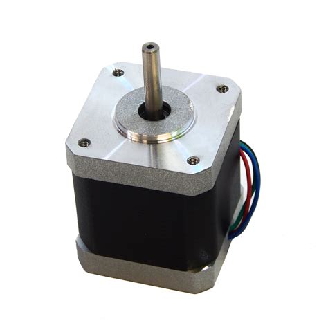
NEMA 17 Stepper Motors
NEMA 17 is a standardized frame size for stepper motors, as defined by the National Electrical Manufacturers Association (NEMA). The “17” in NEMA 17 refers to the motor’s faceplate size, which is approximately 1.7 inches (43.2 mm) square.
Characteristics of NEMA 17 Stepper Motors
NEMA 17 stepper motors are known for their high torque output relative to their compact size. Some key characteristics of NEMA 17 stepper motors include:
- Frame size: 1.7 inches (43.2 mm) square
- Holding torque: Typically ranges from 0.2 to 5.0 N·m (28 to 700 oz·in)
- Step angle: Commonly 1.8° or 0.9° per step (200 or 400 steps per revolution)
- Current rating: Usually between 0.5 to 2.0 A per phase
- Voltage rating: Typically 12 to 48 V DC
- Shaft diameter: Often 5 mm (0.197 inches)
Applications of NEMA 17 Stepper Motors
NEMA 17 stepper motors are widely used in various applications, such as:
- 3D printers
- CNC machines
- Robotics
- Automation systems
- Textile machinery
- Medical devices
- Surveillance cameras
- Laser cutters
- Packaging machines

Working Principle of NEMA 17 Stepper Motors
Most NEMA 17 stepper motors are hybrid stepper motors, which combine the features of both PM and VR stepper motors. The working principle of a hybrid NEMA 17 stepper motor can be explained as follows:
Stator and Rotor Construction
The stator of a hybrid NEMA 17 stepper motor consists of a series of electromagnets arranged in a circular pattern. Each electromagnet is formed by a coil of wire wound around a toothed iron core. The number of electromagnets in the stator determines the number of phases of the motor, which is typically two or four.
The rotor of a hybrid NEMA 17 stepper motor is a permanent magnet with teeth on its circumference. The number of teeth on the rotor is usually 50, which results in a step angle of 1.8° (360° ÷ 50 = 7.2°, and 7.2° ÷ 4 = 1.8° for a 4-phase motor).
Stepping Sequence
To rotate the motor, the electromagnets in the stator are energized in a specific sequence. Each time the sequence is advanced, the rotor aligns itself with the energized electromagnets, causing the motor to rotate by one step.
For example, in a 4-phase hybrid NEMA 17 stepper motor, the stepping sequence might be:
- Phase A energized: Rotor aligns with Phase A electromagnets.
- Phase B energized: Rotor rotates 1.8° to align with Phase B electromagnets.
- Phase C energized: Rotor rotates another 1.8° to align with Phase C electromagnets.
- Phase D energized: Rotor rotates another 1.8° to align with Phase D electromagnets.
This sequence is then repeated to achieve continuous rotation. By reversing the sequence, the motor can be made to rotate in the opposite direction.
Microstepping
In addition to full-step mode, many NEMA 17 stepper motors support microstepping. Microstepping is a technique that allows the motor to rotate in smaller increments than the full-step angle. This is achieved by applying intermediate current levels to the phases, causing the rotor to align at intermediate positions between the full-step positions.
Common microstepping resolutions for NEMA 17 stepper motors include:
- Half-step: 0.9° per step (400 steps per revolution)
- Quarter-step: 0.45° per step (800 steps per revolution)
- Eighth-step: 0.225° per step (1600 steps per revolution)
- Sixteenth-step: 0.1125° per step (3200 steps per revolution)
Microstepping improves the motor’s resolution and smoothness of rotation but may reduce the available torque.

Controlling NEMA 17 Stepper Motors
To control a NEMA 17 stepper motor, a stepper motor driver is required. The driver translates step and direction commands from a controller (such as a microcontroller or a computer) into the appropriate sequence of current levels for the motor’s phases.
Stepper Motor Drivers
Some common stepper motor drivers for NEMA 17 motors include:
- A4988
- DRV8825
- TB6600
- TMC2208
- TMC2209
These drivers typically support microstepping and provide current limiting and protection features.
Connecting a NEMA 17 Stepper Motor to a Driver
To connect a NEMA 17 stepper motor to a driver, the following connections are typically required:
- Phase A coil: Connected to the driver’s A+ and A- outputs
- Phase B coil: Connected to the driver’s B+ and B- outputs
- (For 4-phase motors) Phase C coil: Connected to the driver’s C+ and C- outputs
- (For 4-phase motors) Phase D coil: Connected to the driver’s D+ and D- outputs
The driver’s step and direction inputs are connected to the controller, and the driver’s power supply inputs are connected to a suitable DC power source.
Controlling the Motor
To control the motor, the controller sends step and direction commands to the driver. Each step command causes the driver to advance the stepping sequence by one increment, while the direction command determines the rotation direction (clockwise or counterclockwise).
The speed of rotation is determined by the frequency of the step commands. Higher frequencies result in faster rotation, while lower frequencies result in slower rotation.

Advantages and Disadvantages of NEMA 17 Stepper Motors
Advantages
- Precise position control
- High torque output
- Good repeatability
- No feedback sensor required for open-loop control
- Low cost compared to servo motors
- Wide range of available sizes and specifications
Disadvantages
- May exhibit resonance and vibration at certain speeds
- Can lose steps if overloaded or operated at excessive speeds
- Lower efficiency compared to DC motors
- Requires a stepper motor driver for operation
Frequently Asked Questions (FAQ)
-
What is the holding torque of a NEMA 17 stepper motor?
The holding torque of a NEMA 17 stepper motor varies depending on the specific model but typically ranges from 0.2 to 5.0 N·m (28 to 700 oz·in). -
Can I use a NEMA 17 stepper motor without a driver?
No, a stepper motor driver is required to control a NEMA 17 stepper motor. The driver translates step and direction commands from a controller into the appropriate sequence of current levels for the motor’s phases. -
What is the difference between a unipolar and bipolar NEMA 17 stepper motor?
A unipolar NEMA 17 stepper motor has six leads (two for each phase and a common center tap), while a bipolar NEMA 17 stepper motor has four leads (two for each phase). Unipolar motors are simpler to control but have lower torque output compared to bipolar motors. -
How do I choose the right NEMA 17 stepper motor for my application?
When choosing a NEMA 17 stepper motor, consider factors such as the required torque, speed, step angle, current rating, and voltage rating. Also, ensure that the motor’s specifications are compatible with your stepper motor driver and power supply. -
Can I use a NEMA 17 stepper motor for continuous rotation applications?
Yes, NEMA 17 stepper motors can be used for continuous rotation applications. However, they may exhibit resonance and vibration at certain speeds, which can be mitigated by using microstepping or by operating the motor at a different speed range.
| Characteristic | Typical Range |
|---|---|
| Holding Torque | 0.2 to 5.0 N·m (28 to 700 oz·in) |
| Step Angle | 1.8° or 0.9° per step (200 or 400 steps per revolution) |
| Current Rating | 0.5 to 2.0 A per phase |
| Voltage Rating | 12 to 48 V DC |
| Shaft Diameter | 5 mm (0.197 inches) |
Conclusion
NEMA 17 stepper motors are versatile and widely used in applications requiring precise position control, such as 3D printers, CNC machines, and robotics. Their high torque output, compact size, and relatively low cost make them an attractive choice for many projects.
By understanding the working principle, control methods, and characteristics of NEMA 17 stepper motors, users can effectively integrate these motors into their designs and achieve the desired motion control performance.


Leave a Reply