Introduction to Rotary Encoders
A rotary encoder is an electro-mechanical device that converts the angular position or motion of a shaft or axle to analog or digital output signals. Rotary encoders are widely used in various applications, such as industrial controls, robotics, automotive systems, and computer peripherals, to measure rotation, position, and speed.
There are two main types of rotary encoders:
- Absolute Encoders
- Incremental Encoders
Absolute Encoders
Absolute encoders provide a unique digital code for each distinct angle of the shaft. They maintain position information even when power is removed from the system. The output of an absolute encoder indicates the current position of the shaft without the need to return to a reference position.
Incremental Encoders
Incremental encoders generate a specific number of equally spaced pulses per revolution (PPR) or per inch or mm of motion. They provide information about the relative position of the shaft, which is determined by counting pulses from a reference point. Incremental encoders are more common and cost-effective compared to absolute encoders.
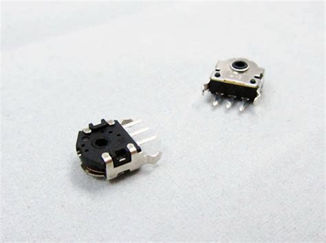
The Working Principle of a Mouse Rotary Encoder
A mouse rotary encoder is a type of incremental encoder commonly used in computer mice to track the rotation of the scroll wheel. It consists of several key components:
- Encoder Wheel
- Light Source (LED)
- Photosensor
Encoder Wheel
The encoder wheel is a circular disk with a series of evenly spaced apertures or slits around its circumference. As the wheel rotates, the apertures alternately allow and block light from passing through.
Light Source (LED)
A light source, typically an LED, is positioned on one side of the encoder wheel. It emits a constant beam of light that shines through the apertures of the encoder wheel.
Photosensor
On the opposite side of the encoder wheel, a photosensor (such as a phototransistor or photodiode) detects the light that passes through the apertures. As the wheel rotates, the photosensor generates electrical pulses corresponding to the alternating light and dark pattern created by the apertures.

Quadrature Encoding
Most mouse rotary encoders utilize quadrature encoding to determine the direction and magnitude of rotation. Quadrature encoding involves using two photosensors (A and B) positioned slightly offset from each other, typically by a quarter of the aperture pitch.
As the encoder wheel rotates, the two photosensors generate two square wave signals (A and B) that are 90 degrees out of phase with each other. The relative phase difference between signals A and B indicates the direction of rotation.
- If signal A leads signal B, the rotation is clockwise (CW).
- If signal B leads signal A, the rotation is counterclockwise (CCW).
The number of pulses generated by the photosensors during a complete rotation of the encoder wheel determines the resolution of the encoder, expressed in pulses per revolution (PPR).

Connecting a Mouse Rotary Encoder to an Arduino
To interface a mouse rotary encoder with an Arduino, you’ll need to make the following connections:
- Connect the encoder’s power pins (VCC and GND) to the Arduino’s 5V and GND pins, respectively.
- Connect the encoder’s output signals (A and B) to two digital input pins on the Arduino, such as pins 2 and 3.
Here’s a sample wiring diagram:
Mouse Rotary Encoder     Arduino
--------------------     -------
        VCC              5V
        GND              GND
        A                Digital Pin 2
        B                Digital Pin 3

Arduino Code for Reading a Mouse Rotary Encoder
To read the rotary encoder’s output and determine the direction and magnitude of rotation, you can use the following Arduino code:
const int encoderPinA = 2;
const int encoderPinB = 3;

volatile int encoderPos = 0;
volatile int lastEncoderPos = 0;

void setup() {
  pinMode(encoderPinA, INPUT_PULLUP);
  pinMode(encoderPinB, INPUT_PULLUP);

  attachInterrupt(digitalPinToInterrupt(encoderPinA), handleEncoderInterrupt, CHANGE);

  Serial.begin(9600);
}

void loop() {
  if (encoderPos != lastEncoderPos) {
    Serial.print("Encoder Position: ");
    Serial.println(encoderPos);
    lastEncoderPos = encoderPos;
  }
}

void handleEncoderInterrupt() {
  if (digitalRead(encoderPinA) == digitalRead(encoderPinB)) {
    encoderPos++;
  } else {
    encoderPos--;
  }
}
In this code:
- We define the digital pins connected to the encoder’s A and B outputs (
encoderPinAandencoderPinB). - We declare variables to store the current and last encoder position (
encoderPosandlastEncoderPos). - In the
setup()function, we configure the encoder pins as inputs with internal pull-up resistors and attach an interrupt toencoderPinAthat triggers on both rising and falling edges. - In the
loop()function, we check if the encoder position has changed and, if so, print the current position to the serial monitor. - The
handleEncoderInterrupt()function is called whenever there is a change in the state ofencoderPinA. It compares the states of both encoder pins to determine the direction of rotation and increments or decrements theencoderPosvariable accordingly.
Factors Affecting Encoder Performance
Several factors can influence the performance and accuracy of a mouse rotary encoder:
- Resolution: The number of pulses per revolution (PPR) determines the encoder’s resolution. Higher resolution encoders provide more precise position information but may require more processing power to handle the increased pulse count.
- Mechanical Tolerance: The manufacturing tolerances of the encoder wheel and the alignment of the light source and photosensors can affect the accuracy and consistency of the encoder’s output.
- Encoder Wheel Material: The material and surface finish of the encoder wheel can impact its durability and the quality of the light and dark pattern created by the apertures.
- Environmental Factors: Dust, dirt, and other contaminants can accumulate on the encoder wheel and interfere with the light path, leading to erroneous or missed pulses.
- Electrical Noise: Electromagnetic interference (EMI) from nearby electronic devices can introduce noise in the encoder’s output signals, causing false or missed pulses.
Advantages of Using a Mouse Rotary Encoder
Mouse rotary encoders offer several benefits in various applications:
- Precise Position Tracking: Rotary encoders provide accurate and repeatable position information, enabling precise control and measurement of rotation.
- High Resolution: With a sufficient number of pulses per revolution, rotary encoders can achieve high angular resolution, allowing for fine-grained control and detection of small movements.
- Non-Contact Sensing: Rotary encoders use optical sensors, which do not require physical contact with the encoder wheel. This non-contact sensing method reduces wear and tear on the components and increases the encoder’s lifespan.
- Versatility: Rotary encoders can be used in a wide range of applications, from industrial machinery and robotics to consumer electronics and computer peripherals.
- Cost-Effective: Incremental rotary encoders, such as those used in computer mice, are relatively inexpensive compared to other position sensing technologies, making them a cost-effective solution for many applications.
Limitations of Mouse Rotary Encoders
While mouse rotary encoders have many advantages, they also have some limitations to consider:
- Relative Position Measurement: Incremental encoders, like those used in mice, only provide relative position information. They do not maintain absolute position when power is removed, requiring a reference position to be established upon power-up.
- Limited Rotational Range: Mouse rotary encoders typically have a limited rotational range due to the physical constraints of the encoder wheel and the mouse housing. For applications requiring continuous rotation or multiple revolutions, other types of encoders may be more suitable.
- Sensitivity to Environmental Factors: Dust, dirt, and other contaminants can accumulate on the encoder wheel and affect the performance of the optical sensors. Regular cleaning and maintenance may be necessary to ensure reliable operation.
- Interference and Noise: Rotary encoders can be susceptible to electromagnetic interference and electrical noise, which can cause false or missed pulses in the output signals. Proper shielding and filtering techniques may be required to mitigate these issues.
Frequently Asked Questions (FAQ)
-
Q: What is the difference between absolute and incremental rotary encoders?
A: Absolute encoders provide a unique digital code for each distinct angle of the shaft and maintain position information even when power is removed. Incremental encoders generate pulses as the shaft rotates and provide relative position information that is determined by counting pulses from a reference point. -
Q: How does quadrature encoding work in a mouse rotary encoder?
A: Quadrature encoding uses two photosensors positioned slightly offset from each other to generate two square wave signals that are 90 degrees out of phase. The relative phase difference between the signals indicates the direction of rotation, while the number of pulses determines the magnitude of rotation. -
Q: Can I use a mouse rotary encoder for continuous rotation applications?
A: Mouse rotary encoders typically have a limited rotational range due to the physical constraints of the encoder wheel and the mouse housing. For applications requiring continuous rotation or multiple revolutions, other types of encoders, such as incremental or absolute shaft encoders, may be more suitable. -
Q: How can I improve the performance and reliability of a mouse rotary encoder?
A: To improve the performance and reliability of a mouse rotary encoder, you can take the following measures: regular cleaning and maintenance to remove dust and contaminants, using encoders with higher resolution for more precise position tracking, and implementing proper shielding and filtering techniques to reduce electromagnetic interference and electrical noise. -
Q: Are mouse rotary encoders suitable for high-precision applications?
A: The suitability of mouse rotary encoders for high-precision applications depends on the specific requirements of the application. While mouse encoders can provide reasonably accurate position information, they may not offer the same level of precision as high-end industrial encoders. Factors such as resolution, mechanical tolerance, and environmental conditions should be considered when evaluating the suitability of a mouse rotary encoder for a particular application.
Conclusion
Mouse rotary encoders are essential components in computer mice that enable precise tracking of the scroll wheel’s rotation. By understanding the working principle of these encoders and how to interface them with an Arduino, you can harness their capabilities for various projects and applications.
When using mouse rotary encoders, it’s essential to consider factors such as resolution, mechanical tolerance, and environmental conditions that can affect their performance. By taking appropriate measures, such as regular maintenance and implementing proper shielding and filtering techniques, you can ensure reliable and accurate operation of the encoder.
With their versatility, cost-effectiveness, and non-contact sensing capabilities, mouse rotary encoders offer a valuable solution for a wide range of applications that require precise position tracking and rotational measurement.


Leave a Reply