Introduction to the MCP6004
The MCP6004 is a low power quad operational amplifier (op-amp) integrated circuit from Microchip Technology. This versatile op-amp chip offers excellent performance while consuming very little power, making it an ideal choice for battery-powered and portable applications. In this article, we’ll dive deep into the MCP6004 Datasheet to understand its features, specifications, and typical applications.
Key Features of the MCP6004
The MCP6004 boasts several key features that make it stand out:
- Low power consumption: Operates at supply voltages as low as 1.8V and consumes only 100 μA per amplifier (typical)
- Rail-to-rail input and output: Allows for maximum dynamic range and flexibility in single-supply applications
- Unity gain stable: Suitable for buffer and unity gain applications without external compensation
- Wide bandwidth: Gain-bandwidth product of 1 MHz allows for high-speed operation
- Low input bias current: Typically less than 1 pA which minimizes error in high-impedance applications
- Available in various package options: 14-pin PDIP, 14-pin SOIC, 14-pin TSSOP

MCP6004 Datasheet Overview
Let’s break down the key sections of the MCP6004 datasheet:
Absolute Maximum Ratings
This section specifies the maximum limits the device can withstand without damage. Key parameters include:
| Parameter | Rating |
|---|---|
| Supply Voltage (VDD – VSS) | 6.0V |
| Input Voltage Range | -0.3V to (VDD + 0.3V) |
| Output Short Circuit Current | Continuous |
| Operating Temperature Range | -40°C to +125°C |
| Junction Temperature | 150°C |
Exceeding these limits may cause permanent damage. It’s important to design within these constraints.
Electrical Characteristics
This section details the MCP6004’s DC and AC performance under recommended operating conditions. Some key specifications at VDD = 1.8V, VSS = 0V, TA = 25°C (unless otherwise noted):
| Parameter | Symbol | Min | Typ | Max | Units |
|---|---|---|---|---|---|
| Input Offset Voltage | VOS | – | 2.5 | 7 | mV |
| Input Bias Current | IB | – | 0.2 | 5 | pA |
| Input Common-Mode Voltage Range | VICR | VSS – 0.1 | – | VDD – 1.4 | V |
| Output Voltage Swing High | VOH | VDD – 0.08 | – | – | V |
| Output Voltage Swing Low | VOL | – | – | 105 | mV |
| Supply Current per amplifier | IDD | – | 100 | 175 | μA |
| Gain Bandwidth Product | GBW | 0.3 | 1.0 | – | MHz |
| Slew Rate | SR | 0.2 | 0.7 | – | V/μs |
These specifications help designers determine if the MCP6004 meets their circuit requirements. The typical values represent what most devices exhibit under nominal conditions.
Typical Performance Curves
This section presents graphs that show how certain parameters vary with changes in operating conditions like supply voltage, temperature, and frequency. Some key graphs include:
- Input offset voltage vs. temperature
- Supply current vs. supply voltage
- Open-loop gain and phase vs. frequency
- Output voltage swing vs. supply voltage
- Common-mode rejection ratio vs. frequency
These curves give designers insight into the op-amp’s real-world behavior and help with circuit analysis and simulation.
Application Information
The datasheet provides guidance on using the MCP6004 in various applications. Some key applications include:
-
Single-supply operation: With its rail-to-rail I/O and low voltage capability, the MCP6004 is well-suited for single-supply designs. The datasheet shows example circuits for single-supply Non-inverting amplifiers, inverting amplifiers, and voltage followers.
-
High-impedance sensor interface: The low input bias current of the MCP6004 minimizes error when amplifying signals from high-impedance sources like pH probes, photodiodes, and piezoelectric sensors. An example pH probe amplifier circuit is provided.
-
Low-power active filters: The MCP6004’s low power consumption and wide bandwidth make it a good choice for implementing active filters in portable devices. The datasheet demonstrates a 2-pole low-pass Sallen-Key filter.
-
Portable instrumentation: Battery-powered test equipment can benefit from the MCP6004’s low voltage and low power capabilities. Example circuits include a portable oscilloscope front-end and a handheld digital multimeter.
The application section also covers topics like PCB layout considerations, unused amplifier handling, and input/output protection measures.
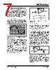
Package and Pinout Information
The datasheet provides mechanical drawings and dimensions for the available package options (PDIP, SOIC, TSSOP). The pinout diagram shows the function of each pin:
| Pin | Name | Description |
|---|---|---|
| 1 | OUTPUT 1 | Output of amplifier 1 |
| 2 | INPUT 1- | Inverting input of amplifier 1 |
| 3 | INPUT 1+ | Non-inverting input of amplifier 1 |
| 4 | VDD | Positive supply |
| 5 | INPUT 2+ | Non-inverting input of amplifier 2 |
| 6 | INPUT 2- | Inverting input of amplifier 2 |
| 7 | OUTPUT 2 | Output of amplifier 2 |
| 8 | OUTPUT 3 | Output of amplifier 3 |
| 9 | INPUT 3- | Inverting input of amplifier 3 |
| 10 | INPUT 3+ | Non-inverting input of amplifier 3 |
| 11 | VSS | Negative supply (Ground) |
| 12 | INPUT 4+ | Non-inverting input of amplifier 4 |
| 13 | INPUT 4- | Inverting input of amplifier 4 |
| 14 | OUTPUT 4 | Output of amplifier 4 |
This information is crucial for properly designing the PCB footprint and making the right connections to the chip.

Advantages of the MCP6004
The MCP6004 has several advantages that make it a popular choice for low-power, precision analog applications:
-
Quad amplifier in a single package: Having four op-amps in one chip saves board space and reduces component count compared to using multiple single or dual op-amp packages.
-
Precision specifications: The low input offset voltage and low bias current enable accurate signal conditioning for sensors with small output voltages or high impedances.
-
Versatility: The MCP6004’s key specs are not overly specialized, making it adaptable to a wide range of applications beyond those mentioned in the datasheet.
-
Cost effectiveness: Compared to other precision quad op-amps, the MCP6004 offers excellent value, especially for high-volume, cost-sensitive products.
-
Reliable operation: Microchip’s advanced CMOS process and robust design ensure consistent performance and reliability over the device’s lifetime.

MCP6004 vs. Similar Op-Amps
Let’s see how the MCP6004 compares to some similar low-power quad op-amps:
| Parameter | MCP6004 | OPA4349 (TI) | LTC6084 (Analog Devices) |
|---|---|---|---|
| Supply Voltage Range (V) | 1.8 to 6 | 2.5 to 5.5 | 1.8 to 5.5 |
| Quiescent Current / amplifier (μA) | 100 | 60 | 9.5 |
| Gain Bandwidth Product (MHz) | 1 | 33 | 0.13 |
| Input Offset Voltage (mV) | 2.5 | 0.5 | 0.15 |
| Input Bias Current (pA) | 0.2 | 0.5 | 0.03 |
| Slew Rate (V/μs) | 0.7 | 10 | 0.015 |
| Packages Available | PDIP, SOIC, TSSOP | SOIC, MSOP | SOIC, SSOP |
The OPA4349 is faster and has lower offset but consumes more power. The LTC6084 has the lowest power and best DC precision but is much slower. The MCP6004 offers a good balance of power, precision, and speed for general-purpose applications.
Typical MCP6004 Applications
Some common applications that can benefit from the MCP6004’s features:
-
Battery-powered devices: Wireless sensors, wearables, IoT nodes, handheld instruments.
-
Portable medical devices: Glucometers, pulse oximeters, blood pressure monitors.
-
Environment sensors: Temperature, humidity, pressure, gas, and Air Quality Sensors.
-
Industrial control: Process monitoring, PID controllers, isolated analog I/O.
-
Audio/Video: Microphone preamps, equalizers, volume controls, video filters.
This is not an exhaustive list by any means. The MCP6004’s versatility makes it adaptable to countless analog signal path scenarios.
FAQ
1. Can the MCP6004 operate from a single 5V supply?
Yes, the MCP6004 has a maximum supply voltage rating of 6V, so it can safely operate from a 5V supply. Just ensure that the input signals are within the input common-mode range, which is typically 0.1V above the negative rail (ground) to 1.4V below the positive rail.
2. How do I select the right feedback resistors for a non-inverting amplifier?
The gain of a non-inverting amplifier is given by:
Gain = 1 + (Rf / Rin)
Where Rf is the feedback resistor from the op-amp output to the non-inverting input, and Rin is the resistor from the non-inverting input to ground.
To minimize error due to the op-amp’s input bias current, keep the parallel combination of Rf and Rin below 100 kΩ. A common 1% resistor value for Rin is 10 kΩ, so for a gain of 11, Rf would be 100 kΩ.
3. What is the difference between rail-to-rail input and rail-to-rail output?
Rail-to-rail input means that the op-amp can handle input voltages very close to the supply rails (e.g., within 0.1V). This allows for the maximum input signal range, especially in low-voltage single-supply applications.
Rail-to-rail output means that the op-amp can swing its output voltage very close to the supply rails (e.g., within a few millivolts). This allows for the maximum output signal range and the ability to drive the output to the rails without clipping.
The MCP6004 has both rail-to-rail input and output, making it ideal for single-supply operation.
4. Can I use the MCP6004 in a split-supply configuration?
Yes, even though the MCP6004 is optimized for single-supply operation, it can also work with split supplies (e.g., ±2.5V). In this case, the input and output voltages can swing above and below ground, and the lower supply (VSS) becomes the negative voltage instead of ground. The same supply voltage limits apply, so the total supply voltage (VDD – VSS) should not exceed 6V.
5. How do I reduce noise pickup in my MCP6004 circuit?
Some key practices to minimize noise in op-amp circuits:
- Keep the input traces short and away from noisy digital lines
- Use a ground plane on the PCB to provide a low-impedance return path
- Decouple the power supply pins with ceramic capacitors (0.1 μF to 10 μF) close to the chip
- Use shielded cables for sensitive input signals
- Add an RC low-pass filter at the input to limit high-frequency noise
- Consider using a Faraday cage around sensitive analog sections
By understanding the noise sources in your environment and applying these techniques, you can achieve a robust, low-noise design with the MCP6004.
Conclusion
The MCP6004 low-power quad op-amp is a versatile and cost-effective choice for a wide range of precision analog applications, especially those requiring single-supply operation and portability. By carefully reviewing the MCP6004 datasheet and following the application guidelines, designers can unlock the full potential of this powerful yet efficient chip. Whether you’re building a battery-powered sensor node, a handheld instrument, or an industrial control system, the MCP6004 provides the right combination of performance, power savings, and flexibility to help you succeed.


Leave a Reply