Introduction to Logic Gates and Truth Tables
Logic gates are the fundamental building blocks of digital electronics. They are used to perform logical operations on binary inputs and produce a binary output based on the inputs. Logic gates are essential components in the design of digital circuits, such as microprocessors, memory devices, and other digital systems.
Truth tables are a way to represent the behavior of logic gates. They show the output of a logic gate for all possible combinations of inputs. Truth tables are an essential tool for designing and analyzing digital circuits.
In this article, we will explore the different types of logic gates and their corresponding truth tables. We will also discuss how to read and interpret truth tables, and how to use them to design and analyze digital circuits.
Types of Logic Gates
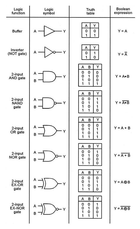
There are seven basic types of logic gates:
- AND gate
- OR gate
- NOT gate (inverter)
- NAND gate
- NOR gate
- XOR gate (exclusive OR)
- XNOR gate (exclusive NOR)
Each logic gate has a unique symbol and performs a specific logical operation on its inputs. Let’s take a closer look at each type of logic gate and its corresponding truth table.
AND Gate
The AND gate is a logic gate that performs the logical AND operation on its inputs. It produces a high output (1) only when all of its inputs are high (1). If any of the inputs are low (0), the output will be low (0).
The symbol for an AND gate is:
   ___
A--|   \
   |AND |-- Y
B--|___/
The truth table for a two-input AND gate is:
| A | B | Y |
|---|---|---|
| 0 | 0 | 0 |
| 0 | 1 | 0 |
| 1 | 0 | 0 |
| 1 | 1 | 1 |
As you can see from the truth table, the output (Y) is only high (1) when both inputs (A and B) are high (1).
OR Gate
The OR gate is a logic gate that performs the logical OR operation on its inputs. It produces a high output (1) when at least one of its inputs is high (1). If all of the inputs are low (0), the output will be low (0).
The symbol for an OR gate is:
   ___
A--|   \
   | OR |-- Y
B--|___/
The truth table for a two-input OR gate is:
| A | B | Y |
|---|---|---|
| 0 | 0 | 0 |
| 0 | 1 | 1 |
| 1 | 0 | 1 |
| 1 | 1 | 1 |
As you can see from the truth table, the output (Y) is high (1) when at least one of the inputs (A or B) is high (1).
NOT Gate (Inverter)
The NOT gate, also known as an inverter, is a logic gate that performs the logical NOT operation on its input. It produces the opposite of its input, i.e., if the input is high (1), the output will be low (0), and vice versa.
The symbol for a NOT gate is:
   ___
A--|NOT|-- Y
   ---
The truth table for a NOT gate is:
| A | Y |
|---|---|
| 0 | 1 |
| 1 | 0 |
As you can see from the truth table, the output (Y) is always the opposite of the input (A).
NAND Gate
The NAND gate is a logic gate that performs the logical NAND (NOT-AND) operation on its inputs. It produces a low output (0) only when all of its inputs are high (1). If any of the inputs are low (0), the output will be high (1).
The symbol for a NAND gate is:
   _____
A--|    \
   |NAND|-- Y
B--|____/
The truth table for a two-input NAND gate is:
| A | B | Y |
|---|---|---|
| 0 | 0 | 1 |
| 0 | 1 | 1 |
| 1 | 0 | 1 |
| 1 | 1 | 0 |
As you can see from the truth table, the output (Y) is low (0) only when both inputs (A and B) are high (1).
NOR Gate
The NOR gate is a logic gate that performs the logical NOR (NOT-OR) operation on its inputs. It produces a high output (1) only when all of its inputs are low (0). If any of the inputs are high (1), the output will be low (0).
The symbol for a NOR gate is:
   _____
A--|    \
   | NOR|-- Y
B--|____/
The truth table for a two-input NOR gate is:
| A | B | Y |
|---|---|---|
| 0 | 0 | 1 |
| 0 | 1 | 0 |
| 1 | 0 | 0 |
| 1 | 1 | 0 |
As you can see from the truth table, the output (Y) is high (1) only when both inputs (A and B) are low (0).
XOR Gate (Exclusive OR)
The XOR gate, also known as an exclusive OR gate, is a logic gate that performs the logical XOR operation on its inputs. It produces a high output (1) when the inputs are different, i.e., one input is high (1) and the other is low (0). If both inputs are the same, either both high (1) or both low (0), the output will be low (0).
The symbol for an XOR gate is:
   ___
A--|   \
   |XOR|-- Y
B--|___/
The truth table for a two-input XOR gate is:
| A | B | Y |
|---|---|---|
| 0 | 0 | 0 |
| 0 | 1 | 1 |
| 1 | 0 | 1 |
| 1 | 1 | 0 |
As you can see from the truth table, the output (Y) is high (1) only when the inputs (A and B) are different.
XNOR Gate (Exclusive NOR)
The XNOR gate, also known as an exclusive NOR gate, is a logic gate that performs the logical XNOR operation on its inputs. It produces a high output (1) when the inputs are the same, i.e., both inputs are high (1) or both inputs are low (0). If the inputs are different, one input is high (1) and the other is low (0), the output will be low (0).
The symbol for an XNOR gate is:
   _____
A--|     \
   |XNOR|-- Y
B--|_____/
The truth table for a two-input XNOR gate is:
| A | B | Y |
|---|---|---|
| 0 | 0 | 1 |
| 0 | 1 | 0 |
| 1 | 0 | 0 |
| 1 | 1 | 1 |
As you can see from the truth table, the output (Y) is high (1) only when the inputs (A and B) are the same.

Reading and Interpreting Truth Tables
Truth tables are a simple and effective way to represent the behavior of logic gates. They show the output of a logic gate for all possible combinations of inputs.
To read a truth table, start by looking at the input columns. Each row in the truth table represents a different combination of inputs. The output column shows the corresponding output for each combination of inputs.
For example, let’s look at the truth table for a two-input AND gate:
| A | B | Y |
|---|---|---|
| 0 | 0 | 0 |
| 0 | 1 | 0 |
| 1 | 0 | 0 |
| 1 | 1 | 1 |
The first row shows the output when both inputs (A and B) are low (0). The second row shows the output when input A is low (0) and input B is high (1). The third row shows the output when input A is high (1) and input B is low (0). The fourth row shows the output when both inputs (A and B) are high (1).
By examining the truth table, we can see that the output (Y) is only high (1) when both inputs (A and B) are high (1). For all other combinations of inputs, the output is low (0).

Using Truth Tables to Design and Analyze Digital Circuits
Truth tables are an essential tool for designing and analyzing digital circuits. They allow us to determine the behavior of a logic gate or a combination of logic gates for all possible inputs.
When designing a digital circuit, we can use truth tables to determine the required logic gates and their interconnections. By examining the desired output for each combination of inputs, we can select the appropriate logic gates and connect them to achieve the desired behavior.
For example, let’s say we want to design a digital circuit that controls a motor based on two sensors. The motor should turn on only when both sensors are active. We can use a truth table to determine the required logic gate:
| Sensor 1 | Sensor 2 | Motor |
|---|---|---|
| 0 | 0 | 0 |
| 0 | 1 | 0 |
| 1 | 0 | 0 |
| 1 | 1 | 1 |
From the truth table, we can see that the desired behavior matches the truth table for an AND gate. Therefore, we can use an AND gate to control the motor based on the two sensors.
When analyzing a digital circuit, we can use truth tables to verify its behavior. By examining the truth table for each logic gate in the circuit and comparing it to the desired behavior, we can identify any errors or inconsistencies in the design.

Frequently Asked Questions (FAQ)
1. What is a logic gate?
A logic gate is an electronic circuit that performs a logical operation on one or more binary inputs and produces a single binary output. Logic gates are the fundamental building blocks of digital circuits.
2. What is a truth table?
A truth table is a tabular representation of the behavior of a logic gate or a combination of logic gates. It shows the output of the logic gate for all possible combinations of inputs.
3. How many types of logic gates are there?
There are seven basic types of logic gates: AND, OR, NOT (inverter), NAND, NOR, XOR (exclusive OR), and XNOR (exclusive NOR).
4. What is the difference between an AND gate and an OR gate?
An AND gate produces a high output only when all of its inputs are high, while an OR gate produces a high output when at least one of its inputs is high.
5. How are truth tables used in digital circuit design?
Truth tables are used to determine the required logic gates and their interconnections in a digital circuit. By examining the desired output for each combination of inputs, designers can select the appropriate logic gates and connect them to achieve the desired behavior.
Conclusion
Logic gates and truth tables are essential concepts in digital electronics. Logic gates perform logical operations on binary inputs and produce binary outputs, while truth tables provide a tabular representation of the behavior of logic gates.
Understanding the different types of logic gates and their corresponding truth tables is crucial for designing and analyzing digital circuits. By using truth tables, designers can determine the required logic gates and their interconnections to achieve the desired behavior.
As digital technology continues to advance, the importance of logic gates and truth tables will only continue to grow. Whether you are a student studying digital electronics or a professional working in the field, a solid understanding of these concepts is essential for success.


Leave a Reply