Introduction to LM3914
The LM3914 is a versatile and widely-used integrated circuit (IC) that functions as a dot/bar display driver. This IC is designed to sense analog voltage levels and drive 10 LEDs, providing a linear analog display. The LM3914 is commonly used in various applications such as audio level meters, battery level indicators, and temperature gauges.
Key Features of LM3914
The LM3914 offers several key features that make it a popular choice for linear analog displays:
- Drives 10 LEDs for dot or bar graph display
- Adjustable reference voltage for full-scale calibration
- Programmable input range and LED brightness
- Cascadable for displays requiring more than 10 LEDs
- Internal voltage reference for stable operation
- Low standby current drain suitable for battery-powered applications

How Does the LM3914 Work?
Internal Architecture
The LM3914 consists of the following main components:
- Voltage divider: A resistive voltage divider network that creates 10 equally spaced voltage levels.
- Comparators: 10 comparators that compare the input signal with the voltage divider levels.
- Decoder: A decoder that interprets the comparator outputs and drives the corresponding LEDs.
- Reference voltage: An adjustable reference voltage that sets the full-scale voltage range.
- Mode selector: Determines whether the display operates in dot or bar mode.
Operating Principle
- The input signal is applied to the non-inverting input of each comparator.
- The voltage divider creates 10 equally spaced voltage levels, which are connected to the inverting inputs of the comparators.
- Each comparator compares the input signal with its corresponding voltage level from the divider.
- The comparator outputs are fed to the decoder, which drives the appropriate LED based on the input signal level.
- The reference voltage determines the full-scale voltage range, and the mode selector determines whether the display operates in dot or bar mode.

Pinout and Description
| Pin | Symbol | Description |
|---|---|---|
| 1 | LED 1 | LED 1 output |
| 2 | LED 2 | LED 2 output |
| 3 | LED 3 | LED 3 output |
| 4 | LED 4 | LED 4 output |
| 5 | LED 5 | LED 5 output |
| 6 | LED 6 | LED 6 output |
| 7 | LED 7 | LED 7 output |
| 8 | LED 8 | LED 8 output |
| 9 | Mode | Display mode selection |
| 10 | LED 9 | LED 9 output |
| 11 | LED 10 | LED 10 output |
| 12 | Ref Out | Reference voltage output |
| 13 | Ref Adj | Reference voltage adjustment |
| 14 | V+ | Positive supply voltage |
| 15 | Signal | Signal input |
| 16 | RHI | LED current limit resistor |
| 17 | RLO | LED current limit resistor |
| 18 | GND | Ground |

Configuring the LM3914
Setting the Reference Voltage
The reference voltage determines the full-scale voltage range of the LM3914. It can be set using an external voltage divider connected between the Ref Out (pin 12) and Ref Adj (pin 13) pins. The reference voltage is typically set to 1.25V, but it can be adjusted to suit the application.
Choosing the Display Mode
The LM3914 can operate in two display modes: dot mode and bar mode. The mode is selected using the Mode pin (pin 9). When the Mode pin is left open or connected to V+, the display operates in bar mode. When the Mode pin is connected to ground, the display operates in dot mode.
Setting the LED Current
The LED current is controlled by the resistors connected to the RHI (pin 16) and RLO (pin 17) pins. The LED current can be calculated using the following formula:
ILED = 12.5V / (RHI + RLO)
Typical values for RHI and RLO are 1kΩ to 10kΩ, resulting in LED currents of 1.25mA to 12.5mA.
Application Examples
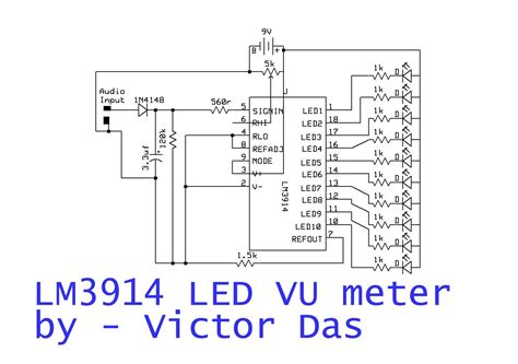
Audio Level Meter
An audio level meter is a common application of the LM3914. The input signal is typically an audio signal from a microphone or line-level source. The LM3914 displays the audio level on a linear scale using 10 LEDs.
               +12V
                |
               [R1] 10kΩ
                |
               [R2] 10kΩ
                |
                |--[C1] 100nF
                |
Audio Input ----|
                |
                |
                |     [LED1] [LED2] ... [LED10]
                |      |      |          |
                |     +-+    +-+        +-+
                |     |1|    |2|        |11|
                |------|Signal LED 1 ... LED 10 LM3914
                |     |18    17         10|
                |     GND    RLO        Mode----|
                |      |                         |
               GND    [R3] 1kΩ                  GND
Battery Level Indicator
The LM3914 can be used to display the battery level in portable devices. The input signal is the battery voltage, and the reference voltage is set to the maximum battery voltage. The LED display indicates the remaining battery capacity.
                        +Battery
                         |
                        [R1] 10kΩ
                         |
                        [R2] 10kΩ
                         |
                         |
                         |     [LED1] [LED2] ... [LED10]
                         |      |      |          |
                         |     +-+    +-+        +-+
                         |     |1|    |2|        |11|
                 Battery-|----|Signal LED 1 ... LED 10 LM3914
                         |     |18    17         10|
                         |     GND    RLO        Mode----|
                         |      |                         |
                        GND    [R3] 1kΩ                  GND
FAQ
-
Q: What is the maximum number of LEDs that can be driven by the LM3914?
A: The LM3914 can drive up to 10 LEDs. However, multiple LM3914s can be cascaded to drive more than 10 LEDs. -
Q: Can the LM3914 be used with a microcontroller?
A: Yes, the LM3914 can be easily interfaced with a microcontroller. The microcontroller can control the display mode, reference voltage, and input signal. -
Q: What is the difference between dot mode and bar mode?
A: In dot mode, only one LED is illuminated at a time, indicating the input signal level. In bar mode, all LEDs up to the input signal level are illuminated, creating a bar graph display. -
Q: Can the LED brightness be adjusted?
A: Yes, the LED brightness can be adjusted by changing the values of the resistors connected to the RHI and RLO pins, which control the LED current. -
Q: What is the maximum input voltage that the LM3914 can handle?
A: The maximum input voltage is limited by the supply voltage (V+). The input signal should not exceed the supply voltage to prevent damage to the IC.
Conclusion
The LM3914 is a versatile and easy-to-use IC for creating linear analog displays with LEDs. Its ability to drive up to 10 LEDs, adjustable reference voltage, and programmable display modes make it suitable for a wide range of applications, from audio level meters to battery level indicators. By understanding its internal architecture, operating principle, and configuration options, you can effectively utilize the LM3914 in your projects.


Leave a Reply