Introduction to the Lm386 Amplifier
The LM386 is an 8-pin integrated circuit (IC) that operates on a supply voltage ranging from 4V to 12V. It features a low quiescent current drain of only 4mA, making it ideal for battery-powered applications. The IC has a fixed gain of 20 (26dB), which can be increased to 200 (46dB) by adding an external capacitor between pins 1 and 8.
Key Features of the LM386 Amplifier
- Low voltage operation (4V to 12V)
- Low quiescent current drain (4mA)
- Fixed gain of 20 (26dB), can be increased to 200 (46dB)
- Wide bandwidth (300kHz)
- Low distortion
- Short-circuit and thermal protection
Basic LM386 Amplifier Circuit
The basic LM386 amplifier circuit consists of the following components:
- LM386 IC
- Input coupling capacitor (C1)
- Output coupling capacitor (C2)
- Bypass capacitor (C3)
- Volume control potentiometer (R1)
- Speaker (8 ohms)
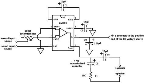
Here’s a schematic diagram of the basic LM386 amplifier circuit:
           +V
            |
            |
            |
            |         C1
            |    |---||---
            |    |        |
            |    |   R1   |
Input ------|----+--/\/\--+----| 3
            |              |
            |              |
            |    C2        |
            +---||---+-----| 5
                     |
                     |
                     |         LM386
                     |   +--------------+
                     |   |              |
                     +---| 2  4  6  7   |---+
                         |              |   |
                         +--------------+   |
                              |  |  |       |
                              |  |  +-------| 1,8
                              |  |          |
                              |  +----------| 4
                              |             |
                              +-------------| GND
                                            |
                                            |
                                            |
                                            |
                                           -V
Step-by-Step Instructions
-
Connect the input signal to the input coupling capacitor (C1). The value of C1 should be chosen based on the desired low-frequency response. A typical value is 0.1uF.
-
Connect the output coupling capacitor (C2) between pin 5 of the LM386 and the positive terminal of the speaker. The value of C2 should be chosen based on the desired low-frequency response. A typical value is 220uF.
-
Connect the bypass capacitor (C3) between pins 7 and 4 of the LM386. This capacitor helps to reduce noise and improve stability. A typical value is 0.1uF.
-
Connect the volume control potentiometer (R1) between the input signal and pin 3 of the LM386. The value of R1 determines the maximum gain of the amplifier. A typical value is 10k ohms.
-
Connect the negative terminal of the speaker to ground.
-
Connect the power supply to pins 6 and 4 of the LM386. Pin 6 should be connected to the positive supply voltage, while pin 4 should be connected to ground.

Increasing the Gain of the LM386 Amplifier
As mentioned earlier, the LM386 has a fixed gain of 20 (26dB), which can be increased to 200 (46dB) by adding an external capacitor between pins 1 and 8. This capacitor, known as the gain-setting capacitor, determines the amount of additional gain provided by the amplifier.
Gain-Setting Capacitor Values
The following table shows the relationship between the gain-setting capacitor value and the corresponding gain:
| Capacitor Value | Gain |
|---|---|
| No capacitor | 20 |
| 10pF | 50 |
| 100pF | 100 |
| 1nF | 150 |
| 10nF | 200 |
To increase the gain of the LM386 amplifier:
-
Connect a capacitor of the appropriate value between pins 1 and 8 of the LM386.
-
Adjust the value of the input coupling capacitor (C1) and the output coupling capacitor (C2) to maintain the desired low-frequency response.

Bass Boost Circuit
The LM386 can be configured to provide a bass boost function, which emphasizes the low-frequency content of the input signal. This is achieved by adding a low-pass filter to the feedback loop of the amplifier.
Bass Boost Circuit Schematic
           +V
            |
            |
            |
            |         C1
            |    |---||---
            |    |        |
            |    |   R1   |
Input ------|----+--/\/\--+----| 3
            |              |
            |              |
            |    C2        |
            +---||---+-----| 5
                     |
                     |
                     |         LM386
                     |   +--------------+
                     |   |              |
                     +---| 2  4  6  7   |---+
                         |              |   |
                         +--------------+   |
                              |  |  |       |
                  R2     C3  |  |  +-------| 1,8
                 /\/\   ||-+ |  |          |
                 |  |      | |  +----------| 4
                 +--+------+ |             |
                              +-------------| GND
                                            |
                                            |
                                            |
                                            |
                                           -V
Step-by-Step Instructions
-
Follow steps 1-6 from the basic LM386 amplifier circuit.
-
Connect a resistor (R2) and a capacitor (C3) in series between pin 1 and ground. The values of R2 and C3 determine the frequency and amount of bass boost. Typical values are 10k ohms for R2 and 0.1uF for C3.
-
Adjust the values of R2 and C3 to achieve the desired bass boost effect.

Tone Control Circuit
A tone control circuit allows the user to adjust the balance between the high and low frequencies of the input signal. This can be achieved by adding a passive tone control network to the input of the LM386 amplifier.
Tone Control Circuit Schematic
                              +V
                               |
                               |
                               |
                               |         C1
                               |    |---||---
                               |    |        |
           R1            R2    |    |   R3   |
Input ---/\/\---+---+--/\/\---+----+--/\/\--+----| 3
                |   |              |
                |   |              |
                |   |    C2        |
                |   +---||---+-----| 5
                |            |
                |            |
                |            |         LM386
                |            |   +--------------+
                |            |   |              |
                |            +---| 2  4  6  7   |---+
                |                |              |   |
                |                +--------------+   |
                |                     |  |  |       |
                |                     |  |  +-------| 1,8
                |                     |  |          |
                |                     |  +----------| 4
                |                     |             |
                +---------------------+-------------| GND
                                                     |
                                                     |
                                                     |
                                                     |
                                                    -V
Step-by-Step Instructions
-
Follow steps 1-6 from the basic LM386 amplifier circuit.
-
Connect a potentiometer (R1) and two fixed resistors (R2 and R3) in series between the input signal and pin 3 of the LM386. The value of R1 determines the range of tone control, while R2 and R3 determine the center frequency. Typical values are 50k ohms for R1, 10k ohms for R2, and 10k ohms for R3.
-
Connect a capacitor (C1) between the wiper of R1 and ground. The value of C1 determines the amount of high-frequency attenuation. A typical value is 0.01uF.
-
Adjust the position of the wiper on R1 to achieve the desired tone balance.
Frequently Asked Questions (FAQ)
- What is the maximum output power of the LM386 amplifier?
-
The LM386 can deliver up to 0.5 watts of power into an 8-ohm load.
-
Can the LM386 be used with higher supply voltages?
-
The LM386 is designed to operate on supply voltages ranging from 4V to 12V. Using higher voltages may cause damage to the IC.
-
How can I reduce the noise in my LM386 amplifier circuit?
-
To reduce noise, ensure that the power supply is well-filtered and decoupled. Use a bypass capacitor (C3) between pins 7 and 4 of the LM386. Keep the input and output wires separated to minimize crosstalk.
-
Can I use the LM386 to drive a 4-ohm speaker?
-
While the LM386 can drive a 4-ohm load, it will produce less output power and may cause the IC to overheat. It is recommended to use an 8-ohm speaker for optimal performance.
-
What is the purpose of the input and output coupling capacitors (C1 and C2)?
- The input coupling capacitor (C1) blocks any DC component from the input signal, preventing it from affecting the bias of the LM386. The output coupling capacitor (C2) blocks the DC offset from the output of the LM386, preventing it from flowing through the speaker.
Conclusion
The LM386 is a versatile and easy-to-use audio power amplifier that can be configured to create various amplification functions. By following the step-by-step instructions provided in this article, you can build a basic amplifier circuit, increase the gain, add bass boost, and incorporate tone control. Experiment with different component values to achieve the desired sound quality and performance for your specific application.


Leave a Reply