Introduction to the LM338 Adjustable Voltage Regulator
The LM338 is a three-terminal adjustable positive voltage regulator designed to supply more than 5A of load current with an output voltage adjustable over a 1.2V to 32V range. It offers several features that make it an attractive choice for various power supply applications:
- Adjustable output voltage range from 1.2V to 32V
- Output current capability in excess of 5A
- Internal current limiting and thermal shutdown protection
- Available in TO-220 and TO-3 packages
LM338 Pin Configuration
The LM338 has three terminals:
- Adjustment (ADJ): Used to set the output voltage
- Output (OUT): Regulated output voltage
- Input (IN): Input voltage supply
Here’s a table showing the pin configuration for the LM338 in TO-220 and TO-3 packages:
| Pin | TO-220 | TO-3 |
|---|---|---|
| Adjustment (ADJ) | 1 | 1 |
| Output (OUT) | 2 | 2 |
| Input (IN) | 3 | 3 |
LM338 Specifications
Electrical Characteristics
| Parameter | Conditions | Min | Typ | Max | Unit |
|---|---|---|---|---|---|
| Output Voltage Range | 1.2 | 32 | V | ||
| Output Current | 5 | A | |||
| Line Regulation | 3V ≤ VIN-VOUT ≤ 35V | 0.01 | 0.03 | %/V | |
| Load Regulation | 10mA ≤ IOUT ≤ 5A | 0.1 | 0.3 | % | |
| Adjustment Pin Current | 45 | 100 | µA | ||
| Ripple Rejection | 10Hz ≤ f ≤ 100kHz | 65 | dB | ||
| Output Noise Voltage | 10Hz ≤ f ≤ 100kHz | 0.003 | % of VOUT |
Absolute Maximum Ratings
| Parameter | Value | Unit |
|---|---|---|
| Input-Output Voltage Differential | 40 | V |
| Power Dissipation | Internally Limited | |
| Operating Junction Temperature Range | 0 to 125 | °C |
| Storage Temperature Range | -65 to 150 | °C |

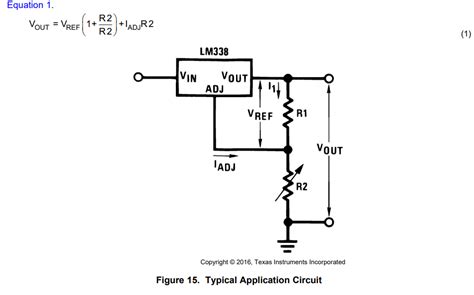
Basic LM338 Circuit
The basic LM338 circuit requires only two external resistors to set the output voltage. The output voltage is given by:
VOUT = 1.25V × (1 + R2 / R1) + IADJ × R2
Where:
– VOUT is the desired output voltage
– R1 and R2 are the resistors that set the output voltage
– IADJ is the adjustment pin current (typically 45µA)
Here’s a schematic of the basic LM338 circuit:
[Insert basic LM338 circuit schematic image here]
To select the appropriate resistor values for R1 and R2, use the following steps:
- Choose a value for R1 between 100Ω and 1kΩ.
- Calculate R2 using the equation: R2 = R1 × ((VOUT / 1.25V) – 1)
Example: For a 5V output with R1 = 240Ω, R2 = 240Ω × ((5V / 1.25V) – 1) = 720Ω.

LM338 Application Circuits
Adjustable Power Supply
An adjustable power supply using the LM338 can be created by adding a potentiometer to the basic circuit. This allows the user to easily adjust the output voltage within the regulator’s range.
[Insert adjustable power supply schematic image here]
In this circuit, a potentiometer (R2) is used in series with a fixed resistor (R1) to set the output voltage. The output voltage is given by:
VOUT = 1.25V × (1 + (R2 + R3) / R1) + IADJ × (R2 + R3)
To ensure proper operation, consider the following:
- Choose R1 and R3 such that the adjustment pin current (IADJ) does not exceed 100µA.
- Use a wire-wound or cermet potentiometer for best stability and temperature coefficient.
Constant Current Regulator
The LM338 can be used as a constant current regulator by exploiting its internal current limiting feature. In this configuration, the LM338 maintains a constant current through the load, regardless of the load resistance or input voltage variations.
[Insert constant current regulator schematic image here]
The constant current is set by the resistor R1 and is given by:
IOUT = 1.25V / R1
Example: For a constant current of 100mA, R1 = 1.25V / 100mA = 12.5Ω.
Battery Charger
The LM338 can be used to create a simple battery charger circuit. The circuit maintains a constant charging current until the battery voltage reaches the desired level, at which point the current decreases to maintain the voltage.
[Insert battery charger schematic image here]
In this circuit, R1 sets the charging current, while R2 and R3 set the float voltage. The charging current and float voltage are given by:
ICHARGE = 1.25V / R1
VFLOAT = 1.25V × (1 + R3 / R2) + IADJ × R3
Example: For a 12V lead-acid battery with a 500mA charging current and 13.8V float voltage, R1 = 2.5Ω, R2 = 1kΩ, and R3 = 10kΩ.

PCB Layout Considerations
When designing a PCB for the LM338 circuit, consider the following:
- Provide adequate heatsinking for the LM338, especially when using it at high output currents.
- Place the input and output capacitors as close to the LM338 as possible to minimize noise and ensure stability.
- Use wide traces for the input, output, and ground connections to minimize voltage drops and improve current handling capacity.
- If using multiple LM338 regulators on the same PCB, ensure proper isolation between the circuits to prevent interaction and instability.
Frequently Asked Questions (FAQ)
-
Q: What is the maximum output current of the LM338?
A: The LM338 can provide output currents in excess of 5A, depending on the input-output voltage differential and the available heatsinking. -
Q: Can the LM338 be used as a negative voltage regulator?
A: No, the LM338 is designed for positive voltage regulation only. For negative voltage regulation, consider using the LM337, which is the complementary part to the LM338. -
Q: What is the minimum input-output voltage differential required for proper regulation?
A: The LM338 requires a minimum input-output voltage differential of 3V for proper regulation. This means that the input voltage must be at least 3V higher than the desired output voltage. -
Q: How can I reduce the output noise of the LM338 circuit?
A: To reduce output noise, consider using larger input and output capacitors, placing them as close to the LM338 as possible. Additionally, using a capacitor with low ESR (Equivalent Series Resistance) can help minimize noise. -
Q: Can I connect multiple LM338 regulators in parallel for increased current capability?
A: While it is possible to connect multiple LM338 regulators in parallel, it is not recommended without proper load balancing and protection circuitry. Uneven current sharing among the regulators can lead to overheating and potential damage to the devices.
Conclusion
The LM338 is a versatile and reliable adjustable voltage regulator that finds applications in a wide range of power supply designs. Its ability to provide high output currents, along with its built-in protection features, makes it an attractive choice for many projects. By understanding the LM338’s specifications, basic circuit configuration, and various application circuits, designers can effectively incorporate this regulator into their designs to create efficient and robust power supply solutions.


Leave a Reply