Introduction to the lm317 Voltage Regulator
The lm317 is a positive voltage regulator that can provide an adjustable output voltage ranging from 1.25V to 37V. It is known for its simplicity, reliability, and easy-to-use design. The lm317 is capable of delivering an output current of up to 1.5A, making it suitable for a wide range of applications, from small-scale hobby projects to industrial-grade power supplies.
Key Features of the lm317
- Adjustable output voltage (1.25V to 37V)
- High output current capability (up to 1.5A)
- Overload protection
- Thermal shutdown
- Wide input voltage range (up to 40V)
- Low quiescent current
- Easy to use and configure
Understanding the lm317 Datasheet
To effectively use the lm317 voltage regulator, it is essential to understand the information provided in its datasheet. The datasheet contains crucial specifications, pin configurations, and application notes that will guide you in designing your voltage regulation circuits.
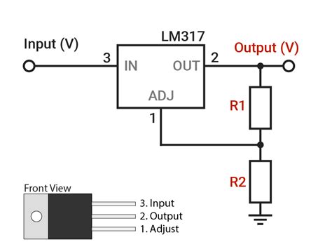
lm317 Pin Configuration
The lm317 comes in various package types, such as TO-220, TO-3, and SOT-223. The most common package is the TO-220, which has three pins:
- Input (VIN)
- Output (VOUT)
- Adjustment (ADJ)
| Pin | Name | Description |
|---|---|---|
| 1 | Input | Connected to the positive input voltage |
| 2 | Output | Connected to the regulated output voltage |
| 3 | Adjustment | Used to set the output voltage |
lm317 Electrical Characteristics
The lm317 datasheet provides essential electrical characteristics that you need to consider when designing your voltage regulation circuits. Some of the key parameters include:
- Output voltage range: 1.25V to 37V
- Maximum output current: 1.5A
- Line regulation: 0.01% / V
- Load regulation: 0.1% / A
- Ripple rejection: 80 dB (typical)
- Output noise voltage: 0.003% / V
- Adjustment pin current: 50µA (typical)

Designing Circuits with the lm317
Now that you have a basic understanding of the lm317 datasheet let’s explore how to design voltage regulation circuits using this versatile component.
Basic lm317 Voltage Regulator Circuit
The most basic lm317 voltage regulator circuit consists of the lm317, two resistors (R1 and R2), and two capacitors (CIN and COUT). The output voltage is set by the ratio of R1 and R2, according to the following formula:
VOUT = 1.25V * (1 + R2 / R1)
To calculate the values of R1 and R2 for a desired output voltage, you can use the following steps:
- Choose a value for R1 (typically between 240Ω and 1kΩ)
- Calculate R2 using the formula: R2 = R1 * (VOUT / 1.25V – 1)
For example, to set the output voltage to 5V with R1 = 240Ω, calculate R2 as follows:
R2 = 240Ω * (5V / 1.25V - 1)
R2 = 240Ω * 3 = 720Ω
Input and Output Capacitor Selection
The input and output capacitors (CIN and COUT) play a crucial role in reducing noise and ensuring stable operation of the lm317 voltage regulator. The lm317 datasheet recommends the following guidelines for selecting these capacitors:
-
CIN: A 0.1µF ceramic capacitor is sufficient for most applications. For input voltages greater than 25V or in high-noise environments, a larger capacitor (1µF or more) may be required.
-
COUT: The output capacitor helps to improve transient response and reduce output ripple. A minimum of 1µF tantalum or 10µF aluminum electrolytic capacitor is recommended. In some cases, a larger capacitor (up to 100µF) may be necessary for improved performance.
Protecting the lm317 from Overcurrent and Overheating
The lm317 features built-in overload and thermal shutdown protection, which helps to prevent damage to the regulator and connected components in case of excessive current draw or overheating. However, it is still recommended to include additional protection measures in your designs, such as:
-
Current limiting resistor: A small resistor (typically 0.1Ω to 1Ω) can be placed in series with the output to limit the maximum current. The value of this resistor should be chosen based on the maximum expected load current and the desired output voltage drop.
-
Heat sink: In applications where the lm317 is expected to dissipate significant power, a heat sink should be used to prevent overheating. The lm317 datasheet provides thermal resistance data that can be used to calculate the required heat sink size based on the expected power dissipation and ambient temperature.

lm317 Application Examples
The lm317 voltage regulator is versatile and can be used in a wide range of applications. Some common examples include:
- Adjustable power supplies
- Battery chargers
- LED drivers
- Motor speed controllers
- Constant current sources
Adjustable Power Supply
One of the most popular applications of the lm317 is in adjustable power supplies. By using a potentiometer in place of R2 in the basic voltage regulator circuit, you can create a power supply with a user-adjustable output voltage.
LED Driver
The lm317 can also be used as a constant current source to drive high-power LEDs. By configuring the regulator in a constant current mode, you can ensure that the LED receives a stable current, regardless of changes in the LED’s forward voltage or the input voltage.

Frequently Asked Questions (FAQ)
-
Q: What is the maximum input voltage for the lm317?
A: The lm317 can handle input voltages up to 40V. However, the input voltage must be at least 3V higher than the desired output voltage for proper regulation. -
Q: Can the lm317 be used as a negative voltage regulator?
A: No, the lm317 is designed for positive voltage regulation only. For negative voltage regulation, you can use the lm337, which is the complementary counterpart of the lm317. -
Q: How do I calculate the power dissipation of the lm317?
A: The power dissipation of the lm317 can be calculated using the following formula:
P = (VIN - VOUT) * IOUT
Where P is the power dissipation, VIN is the input voltage, VOUT is the output voltage, and IOUT is the output current. -
Q: What is the purpose of the adjustment pin on the lm317?
A: The adjustment pin is used to set the output voltage of the lm317. By connecting a resistor divider network between the output, adjustment, and ground pins, you can control the output voltage according to the formula:
VOUT = 1.25V * (1 + R2 / R1) -
Q: Can I connect multiple lm317 regulators in parallel to increase the output current?
A: Yes, you can connect multiple lm317 regulators in parallel to increase the output current capability. However, you should ensure that each regulator has its own set of input and output capacitors and that the adjustment pins are tied together to maintain the same output voltage across all regulators.
Conclusion
The lm317 voltage regulator is a versatile and easy-to-use component that offers a reliable solution for voltage regulation in a wide range of electronic applications. By understanding the lm317 datasheet and its key specifications, you can effectively design circuits that leverage the regulator’s features and capabilities. Whether you are working on a simple hobby project or a complex industrial power supply, the lm317 is a valuable tool in your electronic design arsenal.


Leave a Reply