Introduction to Line Follower Robots
A line follower robot is an autonomous robot that can detect and follow a line drawn on the floor. It is a great project for beginners to learn about robotics and programming. In this article, we will explore the basics of line follower robots and how to make one using an Arduino, Raspberry Pi, or a microcontroller.
What is a Line Follower Robot?
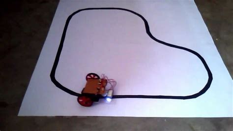
A line follower robot is a type of robot that can detect and follow a line drawn on the floor. The line is usually black on a white background or white on a black background. The robot uses sensors to detect the line and adjust its movement accordingly.
Components of a Line Follower Robot
A line follower robot consists of the following components:
- Microcontroller or development board (Arduino, Raspberry Pi, etc.)
- Motor driver (L293D, L298N, etc.)
- DC motors
- IR sensors or photodiodes
- Battery
- Chassis or body of the robot
How Does a Line Follower Robot Work?
A line follower robot works by using sensors to detect the line and adjust its movement accordingly. The sensors are usually IR sensors or photodiodes that can detect the difference in reflectivity between the line and the background.
IR Sensors
IR sensors consist of an IR LED and an IR photodiode. The IR LED emits infrared light, and the IR photodiode detects the reflected light. When the sensor is over a white surface, most of the light is reflected, and the photodiode receives a high amount of light. When the sensor is over a black surface, most of the light is absorbed, and the photodiode receives a low amount of light.
Photodiodes
Photodiodes are similar to IR sensors but use visible light instead of infrared light. They consist of an LED and a photodiode. The LED emits visible light, and the photodiode detects the reflected light.
Microcontroller
The microcontroller is the brain of the line follower robot. It receives input from the sensors and controls the motors accordingly. The microcontroller is programmed to follow a specific algorithm to keep the robot on the line.
Motor Driver
The motor driver is used to control the DC motors. It receives signals from the microcontroller and adjusts the speed and direction of the motors accordingly.

Making a Line Follower Robot Using Arduino
Arduino is a popular choice for making line follower robots because it is easy to use and has a large community of users.
Components Required
- Arduino UNO
- L293D motor driver
- Two DC motors
- Two IR sensors
- Battery
- Chassis or body of the robot
Circuit Diagram
Code
// Define pins for IR sensors and motors
#define LEFT_SENSOR 2
#define RIGHT_SENSOR 3
#define LEFT_MOTOR_1 4
#define LEFT_MOTOR_2 5
#define RIGHT_MOTOR_1 6
#define RIGHT_MOTOR_2 7

void setup() {
  // Set pins as input/output
  pinMode(LEFT_SENSOR, INPUT);
  pinMode(RIGHT_SENSOR, INPUT);
  pinMode(LEFT_MOTOR_1, OUTPUT);
  pinMode(LEFT_MOTOR_2, OUTPUT);
  pinMode(RIGHT_MOTOR_1, OUTPUT);
  pinMode(RIGHT_MOTOR_2, OUTPUT);
}

void loop() {
  // Read sensor values
  int left_sensor_val = digitalRead(LEFT_SENSOR);
  int right_sensor_val = digitalRead(RIGHT_SENSOR);

  // If both sensors detect the line, move forward
  if (left_sensor_val == LOW && right_sensor_val == LOW) {
    digitalWrite(LEFT_MOTOR_1, HIGH);
    digitalWrite(LEFT_MOTOR_2, LOW);
    digitalWrite(RIGHT_MOTOR_1, HIGH);
    digitalWrite(RIGHT_MOTOR_2, LOW);
  }
  // If left sensor detects the line, turn left
  else if (left_sensor_val == LOW && right_sensor_val == HIGH) {
    digitalWrite(LEFT_MOTOR_1, LOW);
    digitalWrite(LEFT_MOTOR_2, LOW);
    digitalWrite(RIGHT_MOTOR_1, HIGH);
    digitalWrite(RIGHT_MOTOR_2, LOW);
  }
  // If right sensor detects the line, turn right
  else if (left_sensor_val == HIGH && right_sensor_val == LOW) {
    digitalWrite(LEFT_MOTOR_1, HIGH);
    digitalWrite(LEFT_MOTOR_2, LOW);
    digitalWrite(RIGHT_MOTOR_1, LOW);
    digitalWrite(RIGHT_MOTOR_2, LOW);
  }
  // If no sensors detect the line, stop
  else {
    digitalWrite(LEFT_MOTOR_1, LOW);
    digitalWrite(LEFT_MOTOR_2, LOW);
    digitalWrite(RIGHT_MOTOR_1, LOW);
    digitalWrite(RIGHT_MOTOR_2, LOW);
  }
}

Making a Line Follower Robot Using Raspberry Pi
Raspberry Pi is another popular choice for making line follower robots because it is more powerful than Arduino and can run more complex algorithms.
Components Required
- Raspberry Pi
- L298N motor driver
- Two DC motors
- Two IR sensors
- Battery
- Chassis or body of the robot
Circuit Diagram
Code
import RPi.GPIO as GPIO
import time

# Define pins for IR sensors and motors
LEFT_SENSOR = 17
RIGHT_SENSOR = 27
LEFT_MOTOR_1 = 22
LEFT_MOTOR_2 = 23
RIGHT_MOTOR_1 = 24
RIGHT_MOTOR_2 = 25

# Set pins as input/output
GPIO.setmode(GPIO.BCM)
GPIO.setup(LEFT_SENSOR, GPIO.IN)
GPIO.setup(RIGHT_SENSOR, GPIO.IN)
GPIO.setup(LEFT_MOTOR_1, GPIO.OUT)
GPIO.setup(LEFT_MOTOR_2, GPIO.OUT)
GPIO.setup(RIGHT_MOTOR_1, GPIO.OUT)
GPIO.setup(RIGHT_MOTOR_2, GPIO.OUT)

try:
    while True:
        # Read sensor values
        left_sensor_val = GPIO.input(LEFT_SENSOR)
        right_sensor_val = GPIO.input(RIGHT_SENSOR)

        # If both sensors detect the line, move forward
        if left_sensor_val == 0 and right_sensor_val == 0:
            GPIO.output(LEFT_MOTOR_1, True)
            GPIO.output(LEFT_MOTOR_2, False)
            GPIO.output(RIGHT_MOTOR_1, True)
            GPIO.output(RIGHT_MOTOR_2, False)
        # If left sensor detects the line, turn left
        elif left_sensor_val == 0 and right_sensor_val == 1:
            GPIO.output(LEFT_MOTOR_1, False)
            GPIO.output(LEFT_MOTOR_2, False)
            GPIO.output(RIGHT_MOTOR_1, True)
            GPIO.output(RIGHT_MOTOR_2, False)
        # If right sensor detects the line, turn right
        elif left_sensor_val == 1 and right_sensor_val == 0:
            GPIO.output(LEFT_MOTOR_1, True)
            GPIO.output(LEFT_MOTOR_2, False)
            GPIO.output(RIGHT_MOTOR_1, False)
            GPIO.output(RIGHT_MOTOR_2, False)
        # If no sensors detect the line, stop
        else:
            GPIO.output(LEFT_MOTOR_1, False)
            GPIO.output(LEFT_MOTOR_2, False)
            GPIO.output(RIGHT_MOTOR_1, False)
            GPIO.output(RIGHT_MOTOR_2, False)

        time.sleep(0.01)

except KeyboardInterrupt:
    GPIO.cleanup()

Making a Line Follower Robot Using a Microcontroller
Microcontrollers like the PIC or AVR can also be used to make line follower robots. They are cheaper than Arduino or Raspberry Pi but require more programming knowledge.
Components Required
- Microcontroller (PIC or AVR)
- L293D motor driver
- Two DC motors
- Two IR sensors
- Battery
- Chassis or body of the robot
Circuit Diagram
Code
The code for a microcontroller-based line follower robot will vary depending on the specific microcontroller used. However, the basic algorithm remains the same as the Arduino and Raspberry Pi examples.
Conclusion
In this article, we have explored the basics of line follower robots and how to make one using an Arduino, Raspberry Pi, or a microcontroller. We have discussed the components required, the circuit diagrams, and the code needed to make the robot follow a line.
Line follower robots are a great way to learn about robotics and programming. They can be used in various applications, such as automated warehouses, manufacturing plants, and even in competitions.
Frequently Asked Questions (FAQ)
-
What is the purpose of a line follower robot?
A line follower robot is designed to autonomously follow a line drawn on the floor. It can be used in various applications, such as automated warehouses, manufacturing plants, and even in competitions. -
What are the components required to make a line follower robot?
The basic components required to make a line follower robot are: - Microcontroller or development board (Arduino, Raspberry Pi, etc.)
- Motor driver (L293D, L298N, etc.)
- Two DC motors
- Two IR sensors or photodiodes
- Battery
-
Chassis or body of the robot
-
How does a line follower robot detect the line?
A line follower robot uses IR sensors or photodiodes to detect the difference in reflectivity between the line and the background. The sensors are placed on the bottom of the robot, and when they detect the line, they send a signal to the microcontroller, which then adjusts the robot’s movement accordingly. -
Can a line follower robot be made using any microcontroller?
Yes, a line follower robot can be made using any microcontroller, such as Arduino, Raspberry Pi, PIC, or AVR. However, the specific code and circuit diagram may vary depending on the microcontroller used. -
What is the role of the motor driver in a line follower robot?
The motor driver is used to control the DC motors of the robot. It receives signals from the microcontroller and adjusts the speed and direction of the motors accordingly. The motor driver is essential because the microcontroller cannot directly power the motors.
| Component | Description |
|---|---|
| Microcontroller | The brain of the robot that receives input from sensors and controls the motors |
| Motor driver | Used to control the DC motors by receiving signals from the microcontroller |
| DC motors | Provide movement to the robot |
| IR sensors | Detect the difference in reflectivity between the line and the background |
| Battery | Powers the robot and its components |
| Chassis | The body of the robot that holds all the components together |


Leave a Reply