Introduction to Light Sensor Circuit
A light sensor switch circuit is an electronic device that detects the presence or absence of light and triggers a corresponding action, such as turning a device on or off. These circuits are widely used in various applications, including automatic lighting systems, security systems, and energy-saving devices. In this article, we will provide a comprehensive guideline on building your own light sensor circuit.
Components Required for a Light Sensor Circuit
To build a light sensor switch circuit, you will need the following components:
| Component | Description |
|---|---|
| Light Dependent Resistor (LDR) | A resistor whose resistance decreases with increasing light intensity |
| Transistor (e.g., BC547) | An electronic switch that amplifies the signal from the LDR |
| Resistors | Used to control the current flow and voltage levels in the circuit |
| Capacitor | Helps to smooth out voltage fluctuations and prevent false triggering |
| Relay | An electromechanical switch that controls the load (e.g., a lamp or motor) |
| Power Supply | Provides the necessary voltage and current to the circuit |

How a Light Sensor Switch Circuit Works
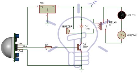
A light sensor switch circuit works by detecting changes in light intensity and converting them into electrical signals. The main component responsible for this is the Light Dependent Resistor (LDR). When light falls on the LDR, its resistance decreases, allowing more current to flow through it. This change in current is then amplified by the transistor, which acts as an electronic switch.
The amplified signal from the transistor is used to control the relay, which in turn switches the load (e.g., a lamp or motor) on or off. The resistors and capacitor in the circuit help to control the sensitivity and stability of the light sensor, preventing false triggering due to minor fluctuations in light intensity.

Step-by-Step Guide to Building a Light Sensor Switch Circuit
Step 1: Gather the necessary components
Ensure that you have all the required components listed in the “Components Required” section before starting the build.
Step 2: Design the circuit schematic
Create a circuit schematic using the following guidelines:
- Connect the LDR in series with a resistor (e.g., 10kΩ) to form a voltage divider.
- Connect the base of the transistor to the junction of the LDR and the resistor.
- Connect the emitter of the transistor to the ground and the collector to one end of the relay coil.
- Connect the other end of the relay coil to the positive power supply.
- Connect a capacitor (e.g., 100μF) in parallel with the relay coil to prevent voltage spikes.
- Connect the load (e.g., a lamp) to the normally open (NO) contacts of the relay.
Step 3: Assemble the circuit on a breadboard
Follow the circuit schematic and assemble the components on a breadboard. Double-check the connections to ensure that everything is in the correct place.
Step 4: Test the circuit
Connect the power supply to the circuit and test its functionality by exposing the LDR to different light levels. The load should turn on when the light intensity is low and turn off when the light intensity is high.
Step 5: Adjust the sensitivity (if needed)
If the circuit is too sensitive or not sensitive enough, adjust the value of the resistor in series with the LDR. Increasing the resistance will make the circuit less sensitive, while decreasing the resistance will make it more sensitive.
Step 6: Transfer the circuit to a permanent board
Once you are satisfied with the circuit’s performance, transfer the components to a permanent circuit board, such as a stripboard or a custom-designed PCB.

Applications of Light Sensor Switch Circuits
Light sensor switch circuits have numerous applications across various industries and domains. Some of the most common applications include:
1. Automatic Lighting Systems
Light sensor switch circuits are widely used in automatic lighting systems, such as street lights, garden lights, and indoor lighting. These systems turn the lights on when the ambient light level falls below a certain threshold and turn them off when the light level rises above the threshold, saving energy and providing convenience.
2. Security Systems
Light sensor circuits are also used in security systems to detect unauthorized access or intrusion. For example, a light sensor can be used to trigger an alarm when a door or window is opened in a dark room, indicating a potential break-in.
3. Energy-Saving Devices
Light sensor circuits can be integrated into various energy-saving devices, such as smart power strips or automatic room light controllers. These devices can turn off appliances or lights when no one is present in the room, reducing energy consumption and utility bills.
4. Photography and Videography
In photography and videography, light sensor circuits are used in devices like flash triggers and automatic camera settings adjusters. These circuits help ensure optimal exposure and lighting conditions for capturing high-quality images and videos.
5. Agriculture and Horticulture
Light sensor circuits are used in agriculture and horticulture to control grow lights, optimize greenhouse conditions, and monitor plant growth. These circuits help ensure that plants receive the optimal amount of light for their growth and development.
Troubleshooting Common Issues with Light Sensor Switch Circuits
While light sensor switch circuits are relatively simple, there are a few common issues that you may encounter during the building or operation process. Here are some troubleshooting tips to help you address these issues:
1. False Triggering
If the circuit is triggering the load even when there is no significant change in light intensity, it may be due to electrical noise or interference. To minimize false triggering, ensure that the circuit is properly grounded and that the capacitor is connected in parallel with the relay coil. You can also increase the value of the resistor in series with the LDR to reduce the circuit’s sensitivity.
2. No Triggering
If the circuit is not triggering the load at all, double-check the connections and ensure that the power supply is providing the correct voltage. Also, verify that the LDR and transistor are functioning correctly by testing them individually with a multimeter.
3. Inconsistent Triggering
If the circuit is triggering inconsistently, it may be due to fluctuations in the ambient light level or the quality of the components used. Ensure that the LDR is positioned in a stable location and not exposed to direct sunlight or artificial light sources that may cause rapid changes in light intensity. Additionally, use high-quality components to minimize performance issues.
FAQ
1. Can I use any type of transistor for the light sensor switch circuit?
While the BC547 transistor is commonly used in light sensor circuits, you can use other NPN transistors with similar specifications. Ensure that the transistor has a suitable current gain (hFE) and can handle the current required by the relay.
2. How do I determine the appropriate resistor values for the circuit?
The resistor values in the circuit depend on the specific components used and the desired sensitivity. As a general guideline, start with a 10kΩ resistor in series with the LDR and adjust the value based on the circuit’s performance. Use Ohm’s law to calculate the appropriate resistor values for other parts of the circuit.
3. Can I use a light sensor switch circuit to control high-power devices?
The light sensor switch circuit described in this article is designed to control low-power devices, such as small lamps or motors. To control high-power devices, you will need to use a relay with an appropriate current and voltage rating. Additionally, ensure that the power supply can provide sufficient current to drive the load.
4. How do I protect the circuit from voltage spikes and surges?
To protect the circuit from voltage spikes and surges, you can include additional components such as transient voltage suppressors (TVS) or metal oxide varistors (MOV) across the power supply and the relay coil. These components help absorb excess energy and prevent damage to the circuit components.
5. Can I use the light sensor switch circuit outdoors?
Yes, you can use the light sensor switch circuit outdoors, but you must take additional precautions to protect the components from weather elements like moisture, dust, and extreme temperatures. Use a weatherproof enclosure to house the circuit and ensure that the components are rated for outdoor use. Additionally, consider using a conformal coating on the circuit board to prevent corrosion and short circuits.
Conclusion
Building a light sensor switch circuit is a straightforward process that can be accomplished with a few basic electronic components. By following the guidelines and steps outlined in this article, you can create a reliable and efficient light sensor circuit for various applications. Remember to start with a clear circuit schematic, test the circuit thoroughly, and make adjustments as needed to achieve the desired performance. With a little practice and experimentation, you can create custom light sensor circuits tailored to your specific needs and requirements.


Leave a Reply