1. Understanding the Basics of LEDs
1.1 What are LEDs?
LEDs are semiconductor devices that emit light when an electric current passes through them. They consist of a p-n junction, where electrons flow from the n-type material to the p-type material, releasing energy in the form of photons. LEDs are available in a wide range of colors, depending on the material used in their construction.
1.2 Advantages of LEDs
LEDs offer several advantages over traditional lighting sources:
– High energy efficiency
– Long lifespan
– Low heat generation
– Instant on/off switching
– Compact size
– Durability and resistance to shock and vibration
1.3 LED Packages and Sizes
LEDs come in various packages and sizes to suit different applications. Some common LED packages include:
| Package | Description |
|---|---|
| Through-hole | LEDs with long leads for insertion into holes on a PCB |
| Surface Mount (SMD) | LEDs designed for direct mounting on the surface of a PCB |
| COB (Chip-on-Board) | Multiple LED chips packaged together on a single substrate |
The size of an LED is often indicated by a four-digit number, such as 0603 or 1206, which represents the dimensions in inches (length x width).
2. LED Characteristics and Specifications
2.1 Forward Voltage and Current
LEDs have a specific forward voltage (Vf) and forward current (If) that must be considered when designing a circuit. The forward voltage is the voltage drop across the LED when it is operating at its nominal current. The forward current is the amount of current required to illuminate the LED at its rated brightness.
2.2 Brightness and Luminous Intensity
The brightness of an LED is measured in lumens (lm), which represents the total amount of light emitted. Luminous intensity, measured in candelas (cd), is the amount of light emitted in a specific direction. These specifications are important when selecting LEDs for specific applications.
2.3 Viewing Angle
The viewing angle of an LED refers to the angle at which the light intensity drops to 50% of its maximum value. A wider viewing angle means the LED can be seen from a greater range of angles, while a narrower viewing angle focuses the light in a specific direction.

3. LED Driver Circuits
3.1 Current Limiting Resistors
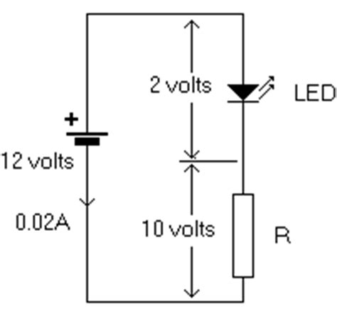
LEDs require a current-limiting resistor to prevent excessive current flow, which can damage the LED. The resistor value is calculated based on the LED’s forward voltage and the desired forward current.
Resistor Value = (Supply Voltage – LED Forward Voltage) / LED Forward Current
3.2 Constant Current Drivers
For more precise control and improved efficiency, constant current LED drivers can be used. These drivers maintain a consistent current through the LED, regardless of variations in the supply voltage or LED forward voltage.
3.3 PWM Dimming
Pulse Width Modulation (PWM) is a technique used to control the brightness of LEDs. By rapidly turning the LED on and off at a high frequency, the perceived brightness can be adjusted. The duty cycle of the PWM signal determines the average current flowing through the LED, thus controlling its brightness.

4. LED Arrays and Matrix Displays
4.1 Series and Parallel Connections
When connecting multiple LEDs in a circuit, they can be arranged in series, parallel, or a combination of both. Series connections require a higher voltage but maintain the same current through all LEDs. Parallel connections require a higher current but allow for individual LED control.
4.2 Multiplexing
Multiplexing is a technique used to control a large number of LEDs using a smaller number of microcontroller pins. By rapidly switching between rows and columns of an LED matrix, each LED can be individually addressed and controlled.
4.3 Shift Registers
Shift registers, such as the 74HC595, can be used to expand the number of output pins on a microcontroller. These devices allow serial data to be converted into parallel outputs, enabling the control of multiple LEDs or LED segments.

5. PCB Design Considerations
5.1 LED Placement and Spacing
When placing LEDs on a circuit board, consider the following factors:
– Adequate spacing between LEDs for heat dissipation
– Orientation and alignment for consistent light output
– Clearance for any lenses or optics
5.2 Trace Width and Thickness
The width and thickness of PCB traces carrying LED current should be sufficient to handle the expected current without excessive voltage drop or heating. Trace width calculators can be used to determine the appropriate dimensions based on the current requirements.
5.3 Thermal Management
LEDs generate heat during operation, which can affect their performance and lifespan. Proper thermal management techniques should be employed, such as:
– Using a heat sink or thermal pad to dissipate heat
– Providing adequate ventilation or cooling
– Selecting LEDs with a suitable thermal resistance
6. LED Optics and Lenses
6.1 Lens Types
LEDs can be paired with various types of lenses to modify the light distribution and beam pattern. Common lens types include:
– Fresnel lenses for collimating light
– Diffusers for softening and spreading light
– TIR (Total Internal Reflection) lenses for efficient beam control
6.2 Reflectors and Light Guides
Reflectors and light guides can be used to direct and shape the light output from LEDs. Reflectors help to focus and intensify the light, while light guides can be used to distribute light evenly over a larger area.
6.3 Color Mixing
Multiple LEDs of different colors can be combined to create a wide range of colors and effects. By using RGB (Red, Green, Blue) LEDs and controlling their individual intensities, a full spectrum of colors can be achieved.
7. Testing and Troubleshooting
7.1 Visual Inspection
Before powering up an LED circuit, perform a visual inspection to check for any obvious issues, such as:
– Correct LED orientation and polarity
– Proper soldering and connections
– Absence of shorts or bridges between traces
7.2 Multimeter Measurements
A multimeter can be used to measure the forward voltage and current of LEDs to ensure they are within the specified range. Continuity tests can also be performed to verify the integrity of connections and traces.
7.3 Current and Voltage Measurements
When troubleshooting an LED circuit, measure the voltage across the LED and the current flowing through it. Compare these values to the expected values based on the LED specifications and circuit design. Adjust the current-limiting resistor or driver circuit as necessary.
Frequently Asked Questions (FAQ)
Q1: What happens if I connect an LED without a current-limiting resistor?
A1: Connecting an LED directly to a voltage source without a current-limiting resistor can cause excessive current flow, which can permanently damage or destroy the LED. Always use an appropriate resistor or current-limiting driver circuit.
Q2: Can I use any resistor value for current limiting?
A2: The resistor value should be calculated based on the LED’s forward voltage, the desired forward current, and the supply voltage. Using the wrong resistor value can result in either insufficient current (dim or no light output) or excessive current (potential LED damage).
Q3: How do I determine the appropriate trace width for my LED circuit?
A3: The appropriate trace width depends on the expected current flow and the desired temperature rise. Use a trace width calculator or consult PCB design guidelines to determine the minimum trace width required for your specific application.
Q4: Can I connect multiple LEDs in parallel without any issues?
A4: Connecting multiple LEDs in parallel can lead to current hogging, where some LEDs draw more current than others due to variations in their forward voltage. This can result in uneven brightness and potentially damage the LEDs. It is recommended to use individual current-limiting resistors or a constant current driver for each LED in parallel.
Q5: What is the difference between luminous intensity and luminous flux?
A5: Luminous intensity, measured in candelas (cd), is the amount of light emitted in a specific direction, while luminous flux, measured in lumens (lm), is the total amount of light emitted by a source in all directions. Luminous intensity is more relevant when considering the directional properties of an LED, while luminous flux is important for determining the overall light output.
Conclusion
Understanding the key aspects of LEDs and their implementation on circuit boards is essential for designing efficient, reliable, and visually appealing LED-based systems. By considering factors such as LED characteristics, driver circuits, PCB design, optics, and testing, you can create LED circuits that meet your specific requirements and deliver optimal performance.
When working with LEDs, always refer to the manufacturer’s datasheets and application notes for detailed specifications and guidelines. Proper design, assembly, and testing practices will help ensure the success of your LED projects, whether you are creating simple indicators or complex lighting systems.
Remember to prioritize safety, efficiency, and reliability in your LED circuit designs, and don’t hesitate to seek guidance from experienced professionals or consult additional resources when needed. With the knowledge gained from this article, you are well-equipped to tackle your next LED circuit board project with confidence and creativity.


Leave a Reply